EVB-USB2524 SMSC, EVB-USB2524 Datasheet - Page 12
EVB-USB2524
Manufacturer Part Number
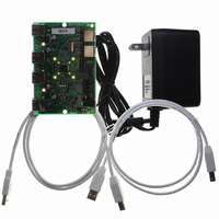
EVB-USB2524
Description
BOARD EVAL USB2524 SHARE/SWITCH
Manufacturer
SMSC
Series
MultiSwitch™r
Specifications of EVB-USB2524
Main Purpose
Interface, USB 2.0 Hub
Embedded
No
Utilized Ic / Part
USB2524
Primary Attributes
Quad Port Hub, High Speed (480Mbps), SMBus
Secondary Attributes
Overcurrent Protection, Port Power Switching, Multi-TT Enabled
Interface Type
USB
Operating Supply Voltage
5 V
Product
Interface Modules
Lead Free Status / RoHS Status
Lead free / RoHS Compliant
For Use With/related Products
USB2524
Other names
638-1044
Available stocks
Company
Part Number
Manufacturer
Quantity
Price
Company:

Part Number:
EVB-USB2524
Manufacturer:
SMSC
Quantity:
135


Chapter 4 Switching Hub Pin Descriptions
Revision 1.91 (08-22-07)
strapping option 0
strapping option 1
Detect Upstream
High-Speed USB
Port 4:3 Green
USB Bus Data
VBUS Power
Port Disable
Port Disable
USB Power
Enable
NAME
Data
LED
&
USBUP_DM[2:1]
USBDN_DM[4:1]
USBDN_DP[4:1]
USBUP_DP[2:1]
VBUS_DET[2:1]
LED_A[4:3]_N/
PRTPWR[4:1]
PRT_DIS[1:0]
PRT_DIS1
SYMBOL
Table 4.1 Switching Hub Pin Descriptions
4-PORT USB 2.0 HUB INTERFACE
UPSTREAM USB 2.0 INTERFACE
TYPE
I/O12
I/O12
IO-U
IO-U
I/O
O
DATASHEET
These pins connect to the upstream USB bus data signals.
Detects state of Upstream VBUS power. The SMSC Hub
monitors VBUS_DET to determine when to assert the
internal D+ pull-up resistor (signalling a connect event).
When designing a detachable hub, this pin must be
connected to the VBUS power pin of the USB port that is
upstream of the hub. (Use of a weak pull-down resistor is
recommended.)
For self-powered applications with a permanently attached
host, this pin must be pulled-up to either 3.3V or 5.0V
(typically VDD33).
These pins connect to the downstream USB peripheral
devices attached to the Hub’s ports.
Enables power to USB peripheral devices (downstream).
The active signal level of the PRTPWR[4] pin is determined
by the Power Polarity Strapping function of the
PRTPWR_POL pin.
Green indicator LED for ports 4 and 3. Will be active low
when LED support is enabled via EEPROM or SMBus. See
PRT_DIS1 function description if the hub is configured by
the internal default configuration.
If the hub is configured by the internal default configuration,
PRT_DIS[1:0] will be sampled at RESET_N negation to
determine if ports [4:2] will be permanently disabled. Also,
the active state of LED_A3_N will be determined as follows:
PRT_DIS[1:0] = '00', All ports are enabled,
LED_A4_N is active high,
LED_A3_N is active high.
PRT_DIS[1:0] = '01', Port 4 is disabled,
LED_A4_N is active high,
LED_A3_N is active low.
PRT_DIS[1:0] = '10', Ports 4 & 3 are disabled,
LED_A4_N is active low,
LED_A3_N is active high.
PRT_DIS[1:0] = '11', Ports 4, 3 & 2 are disabled,
LED_A4_N is active low,
LED_A3_N is active low.
12
FUNCTION
USB MultiSwitch
SMSC USB2524
Datasheet
TM
Hub
Related parts for EVB-USB2524
Image
Part Number
Description
Manufacturer
Datasheet
Request
R

Part Number:
Description:
BOARD EVAL FOR USB2514 48-QFN
Manufacturer:
SMSC
Datasheet:

Part Number:
Description:
Networking Modules & Development Tools LAN7500 USB 2.0 BRD 10/100/1000 GigB
Manufacturer:
SMSC
Datasheet:

Part Number:
Description:
BOARD EVAL FOR USB2514/USB2514I
Manufacturer:
SMSC
Datasheet:

Part Number:
Description:
BOARD EVAL FOR USB2512/USB2512I
Manufacturer:
SMSC
Datasheet:

Part Number:
Description:
BOARD EVAL FOR USB2513/USB2513I
Manufacturer:
SMSC
Datasheet:

Part Number:
Description:
BOARD EVALUATION FOR EMC1043
Manufacturer:
SMSC
Datasheet:
Part Number:
Description:
EVALUATION BOARD FOR USB3311C
Manufacturer:
SMSC
Datasheet:
Part Number:
Description:
EVALUATION BOARD FOR USB3317C
Manufacturer:
SMSC
Datasheet:

Part Number:
Description:
EVALUATION BOARD USB2241-AEZG
Manufacturer:
SMSC
Datasheet:

Part Number:
Description:
BOARD EVALUATION FOR USB2502
Manufacturer:
SMSC
Datasheet:
Part Number:
Description:
BOARD EVALUATION FOR USB2504
Manufacturer:
SMSC
Datasheet:

Part Number:
Description:
EVALUATION BOARD LAN9500-ABZJ
Manufacturer:
SMSC
Datasheet:
Part Number:
Description:
Ethernet Modules & Development Tools LAN9500 Design Kit Low-Cost USB Dongle
Manufacturer:
SMSC
Datasheet:
Part Number:
Description:
Interface Modules & Development Tools Eval BRD-USB2602
Manufacturer:
SMSC
Datasheet: