EVB-USB2524 SMSC, EVB-USB2524 Datasheet - Page 25
EVB-USB2524
Manufacturer Part Number
EVB-USB2524
Description
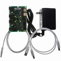
BOARD EVAL USB2524 SHARE/SWITCH
Manufacturer
SMSC
Series
MultiSwitch™r
Specifications of EVB-USB2524
Main Purpose
Interface, USB 2.0 Hub
Embedded
No
Utilized Ic / Part
USB2524
Primary Attributes
Quad Port Hub, High Speed (480Mbps), SMBus
Secondary Attributes
Overcurrent Protection, Port Power Switching, Multi-TT Enabled
Interface Type
USB
Operating Supply Voltage
5 V
Product
Interface Modules
Lead Free Status / RoHS Status
Lead free / RoHS Compliant
For Use With/related Products
USB2524
Other names
638-1044
Available stocks
Company
Part Number
Manufacturer
Quantity
Price
Company:

Part Number:
EVB-USB2524
Manufacturer:
SMSC
Quantity:
135


USB MultiSwitch
Datasheet
SMSC USB2524
7.1.4.10
NUMBER
NUMBER
BIT
BIT
4:3
2:1
7:0
5
0
Register 09h: Non-Removable Device (Reset = 0x00)
TM
PRT_ASSIGN_CFG Port Assignment Configuration:
Hub
STRING_EN
NR_DEVICE
LED_MODE
BIT NAME
BIT NAME
Reserved
Non-Removable Device: Indicates which port(s) include non- removable
devices. ‘0’ = port is removable, ‘1’ = port is non- removable.
Informs the Host if one of the active ports has a permanent device that is un-
detachable from the Hub. (Note: The device must provide its own descriptor
data.)
When using the internal default option, the NON_REM[1:0] pins will designate
the appropriate ports as being non- removable.
Bit 7= Reserved, always = ‘0’.
Bit 6= Reserved, always = ‘0’.
Bit 5= Reserved, always = ‘0’.
Bit 4= 1; Port 4 is disabled.
Bit 3= 1; Port 3 non-removable.
Bit 2= 1; Port 2 non-removable.
Bit 1= 1; Port 1 non-removable.
Bit 0 is Reserved, always = ‘0’.
‘0’ = Port assignment is controlled by hardware interface pins
‘1’ = Port assignment is controlled by:
PORT_ASSIGN_12
PORT_ASSIGN_34
PORT_ASSIGN_56
PORT_ASSIGN_7
Reserved, always = ‘0’.
LED Mode Selection: The LED_A[4:1]_N and LED_B[4:1]_N pins support
several different modes of operation (depending upon OEM implementation of
the LED circuit).
‘00’ = USB Mode, (see
‘01’ = Host Ownership and Port Speed LED indicator, (see
Port Speed LED Indication: on page 45
‘10’ = Basic Host Ownership LED indicator, (see
Indication: on page 44
‘11’ = Same as "00", USB Mode
Warning: Do not enable an LED mode that requires LED pins that are not
available in the specific package being used in the implementation!
Enables String Descriptor Support
‘0’ = String Support Disabled
‘1’ = String Support Enabled
DATASHEET
25
for description)
USB Mode: on page 44
DESCRIPTION
DESCRIPTION
for description)
for description)
Basic Host Owner LED
Revision 1.91 (08-22-07)
Host Ownership and
Related parts for EVB-USB2524
Image
Part Number
Description
Manufacturer
Datasheet
Request
R

Part Number:
Description:
BOARD EVAL FOR USB2514 48-QFN
Manufacturer:
SMSC
Datasheet:

Part Number:
Description:
Networking Modules & Development Tools LAN7500 USB 2.0 BRD 10/100/1000 GigB
Manufacturer:
SMSC
Datasheet:

Part Number:
Description:
BOARD EVAL FOR USB2514/USB2514I
Manufacturer:
SMSC
Datasheet:

Part Number:
Description:
BOARD EVAL FOR USB2512/USB2512I
Manufacturer:
SMSC
Datasheet:

Part Number:
Description:
BOARD EVAL FOR USB2513/USB2513I
Manufacturer:
SMSC
Datasheet:

Part Number:
Description:
BOARD EVALUATION FOR EMC1043
Manufacturer:
SMSC
Datasheet:
Part Number:
Description:
EVALUATION BOARD FOR USB3311C
Manufacturer:
SMSC
Datasheet:
Part Number:
Description:
EVALUATION BOARD FOR USB3317C
Manufacturer:
SMSC
Datasheet:

Part Number:
Description:
EVALUATION BOARD USB2241-AEZG
Manufacturer:
SMSC
Datasheet:

Part Number:
Description:
BOARD EVALUATION FOR USB2502
Manufacturer:
SMSC
Datasheet:
Part Number:
Description:
BOARD EVALUATION FOR USB2504
Manufacturer:
SMSC
Datasheet:

Part Number:
Description:
EVALUATION BOARD LAN9500-ABZJ
Manufacturer:
SMSC
Datasheet:
Part Number:
Description:
Ethernet Modules & Development Tools LAN9500 Design Kit Low-Cost USB Dongle
Manufacturer:
SMSC
Datasheet:
Part Number:
Description:
Interface Modules & Development Tools Eval BRD-USB2602
Manufacturer:
SMSC
Datasheet: