CP2400DK Silicon Laboratories Inc, CP2400DK Datasheet - Page 3
CP2400DK
Manufacturer Part Number
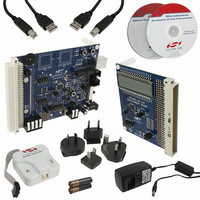
CP2400DK
Description
KIT EVAL SPI LCD DRIVER CP2400
Manufacturer
Silicon Laboratories Inc
Specifications of CP2400DK
Main Purpose
LCD Development
Embedded
Yes
Utilized Ic / Part
CP2400
Primary Attributes
I²C, SMBus Interfaces
Secondary Attributes
Up to 128 segments
Product
Microcontroller Modules
Core Processor
C8051F930
Clock Speed
20 MHz
Interface Type
SPI
Timers
2
Operating Supply Voltage
1.8 V to 3.6 V
Cpu Core
C8051F930
Lead Free Status / RoHS Status
Contains lead / RoHS non-compliant
Lead Free Status / RoHS Status
Lead free / RoHS Compliant, Contains lead / RoHS non-compliant
Other names
336-1858
336-1858
336-1858


1. System Overview .................................................................................................................5
2. Absolute Maximum Ratings.............................................................................................. 11
3. Electrical Characteristics .................................................................................................. 12
4. Pinout and Package Definitions ....................................................................................... 17
5. Clocking Options ...............................................................................................................32
6. Internal Registers and Memory ........................................................................................ 34
7. Interrupt Sources ...............................................................................................................40
8. Reset Sources .................................................................................................................... 47
9. Power Modes......................................................................................................................49
10. Port Input/Output ...............................................................................................................60
11. SmaRTClock (Real Time Clock)........................................................................................ 69
12. LCD Segment Driver ..........................................................................................................83
13. Timers ................................................................................................................................. 92
14. Serial Peripheral Interface (SPI) ..................................................................................... 101
1.1. Typical Connection Diagram ..........................................................................................9
6.1. Accessing Internal Registers and RAM over the SPI Interface .................................... 35
6.2. Accessing Internal Registers and RAM over the SMBus Interface .............................. 36
6.3. Internal Registers .........................................................................................................37
8.1. Reset Initialization ........................................................................................................47
8.2. Power-On Reset........................................................................................................... 48
8.3. External Pin Reset........................................................................................................48
9.1. Normal Mode................................................................................................................ 50
9.2. RAM Preservation Mode .............................................................................................. 50
9.3. Ultra Low Power LCD Mode......................................................................................... 51
9.4. Ultra Low Power SmaRTClock Mode........................................................................... 52
9.5. Shutdown Mode ........................................................................................................... 53
9.6. Determining the ULP Mode Wake-Up Source..............................................................55
9.7. Port Match Functionality in the Ultra Low Power Modes.............................................. 56
9.8. Disabling Secondary Device Functions........................................................................ 58
10.1.Port I/O Modes of Operation ........................................................................................ 61
10.2.Assigning Port I/O Pins to Analog and Digital Functions ............................................. 62
10.3.Active Mode Port Match............................................................................................... 63
10.4.Registers for Accessing and Configuring Port I/O .......................................................65
11.1.SmaRTClock Interface.................................................................................................70
11.2.SmaRTClock Clocking Sources...................................................................................74
11.3.SmaRTClock Timer and Alarm Function .....................................................................77
12.1.Initializing the LCD Segment Driver ............................................................................. 83
12.2.LCD Configuration ....................................................................................................... 84
12.3.LCD Bias Generation and Contrast Adjustment .......................................................... 85
12.4.LCD Timing Generation ............................................................................................... 87
12.5.Mapping ULP Memory to LCD Pins ............................................................................. 90
12.6.Blinking LCD Segments ............................................................................................... 91
13.1.Timer 0 ....................................................................................................................... 92
13.2.Timer 1 ....................................................................................................................... 96
14.1.Signal Descriptions .................................................................................................... 101
14.2.Serial Clock Timing .................................................................................................... 102
Rev. 1.0
CP2400/1/2/3
3
Related parts for CP2400DK
Image
Part Number
Description
Manufacturer
Datasheet
Request
R

Part Number:
Description:
IC LCD DRIVER 48TQFP
Manufacturer:
Silicon Laboratories Inc
Datasheet:
Part Number:
Description:
IC LCD DRIVER 48QFN
Manufacturer:
Silicon Laboratories Inc
Datasheet:

Part Number:
Description:
SMD/C°/SINGLE-ENDED OUTPUT SILICON OSCILLATOR
Manufacturer:
Silicon Laboratories Inc
Part Number:
Description:
Manufacturer:
Silicon Laboratories Inc
Datasheet:
Part Number:
Description:
N/A N/A/SI4010 AES KEYFOB DEMO WITH LCD RX
Manufacturer:
Silicon Laboratories Inc
Datasheet:
Part Number:
Description:
N/A N/A/SI4010 SIMPLIFIED KEY FOB DEMO WITH LED RX
Manufacturer:
Silicon Laboratories Inc
Datasheet:
Part Number:
Description:
N/A/-40 TO 85 OC/EZLINK MODULE; F930/4432 HIGH BAND (REV E/B1)
Manufacturer:
Silicon Laboratories Inc
Part Number:
Description:
EZLink Module; F930/4432 Low Band (rev e/B1)
Manufacturer:
Silicon Laboratories Inc
Part Number:
Description:
I°/4460 10 DBM RADIO TEST CARD 434 MHZ
Manufacturer:
Silicon Laboratories Inc
Part Number:
Description:
I°/4461 14 DBM RADIO TEST CARD 868 MHZ
Manufacturer:
Silicon Laboratories Inc
Part Number:
Description:
I°/4463 20 DBM RFSWITCH RADIO TEST CARD 460 MHZ
Manufacturer:
Silicon Laboratories Inc
Part Number:
Description:
I°/4463 20 DBM RADIO TEST CARD 868 MHZ
Manufacturer:
Silicon Laboratories Inc
Part Number:
Description:
I°/4463 27 DBM RADIO TEST CARD 868 MHZ
Manufacturer:
Silicon Laboratories Inc
Part Number:
Description:
I°/4463 SKYWORKS 30 DBM RADIO TEST CARD 915 MHZ
Manufacturer:
Silicon Laboratories Inc