STEVAL-IPE009V1 STMicroelectronics, STEVAL-IPE009V1 Datasheet - Page 21
STEVAL-IPE009V1
Manufacturer Part Number
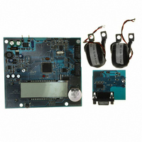
STEVAL-IPE009V1
Description
BOARD EVAL ST72321BR9/STPM14
Manufacturer
STMicroelectronics
Type
Other Power Managementr
Specifications of STEVAL-IPE009V1
Main Purpose
Power Management, Energy/Power Meter
Embedded
Yes, MCU, 8-Bit
Utilized Ic / Part
STPM14, ST72F321BR9T6
Primary Attributes
1-Ph 220 VAC, LCD Displays: No-Load, Reverse, Fraud, or Case Tampering
Secondary Attributes
Up to 4 Tariff Rates, Data Accumulated for Meter Life, Time Stamp for: Tamper, Fraud, Power Failure
Input Voltage
220 V
Product
Power Management Modules
Silicon Manufacturer
ST Micro
Silicon Core Number
ST72321BR9 And STPM14
Features
Continuously Detects, Displays No-Load Condition, Reverse Direction, Fraud And Case Tamper Condition
Lead Free Status / RoHS Status
Lead free / RoHS Compliant
For Use With/related Products
STPM14, ST72321BR9
Other names
497-8434
STEVAL-IPE009V1
STEVAL-IPE009V1


STPM11, STPM12, STPM13, STPM14
7.8
7.9
Error detection
In addition to the no-load condition and the line frequency band, the integration of power can
be suspended also due to detected error on the source signals.
There are two kinds of error detection circuits involved. The first checks all the ∑ Δ signals
from the analog part if any are stacked at 1 or 0 within the 1/128 of f
observation. In case of detected error the corresponding ∑ Δ signal is replaced with an idle
∑ Δ signal, which represents a constant value 0.
Another error, condition occurs if the MOP, MON and LED pin outputs signals are different
from the internal signals that drive them. This can occur if some of this pin is forced to GND
or to some other imposed voltage value.
Tamper detection module (STPM13/14 only)
The STPM13/14 is able to measure the current in both live and neutral wires to implement
an anti-tamper function. When a difference between the two measurements is detected, the
STPM13/14 enters the tamper state. When there is a very small difference between the two
channels, the STPM13/14 is in normal state.
In particular, both channels are not constantly observed. A time multiplex mechanism is
used. During the observation time of the selected channel, its active energy is calculated.
The detection of a tamper condition occurs when the absolute value of the difference
between the two active energy values is greater than a certain percentage of the averaged
energy during the activated tamper module. This percentage value can be selected between
two different values (12.5% and 6.25%) according to the value of the configuration bit CRIT.
The tamper condition will be detected when the following formula is satisfied:
Equation 6
EnergyCH1 - EnergyCH2 > K
or 6.25%.
The detection threshold is much higher than the accuracy difference of the current channels,
which should be less than 0.1%. Some margin should be left for a possible transition effect,
due to accidental synchronism between the actual load current change and the rhythm of
taking the energy samples.
The tamper circuit works if the energies associated with the two current channels will be
both positive or both negative. If the two energies have different signs, the tamper remains
on constantly. However, the channel with the associated higher power is selected for the
final computation of energy.
In single wire mode, the apparent energy rather than active is used for tamper detection.
Detailed operational description
Normal state
The meter is initially set to normal state, i.e. tamper not detected. In such state, we expect
that the values of both load currents should not differ more than the accuracy difference of
the channels. For this reason, we can use an average value of currents of both channels for
the active energy calculation. The average is implemented with the multiplex ratio of 32:32
periods of line per channel. This means that for 32 periods of line voltage, i.e. 640 ms at 50
Hz, the current of the primary channel is used for the calculation followed by another 32
CRIT
Doc ID 13167 Rev 7
(EnergyCH1 + EnergyCH2)/2; where K
CLK
Theory of operation
period of
CRIT
can be 12.5%
21/46
Related parts for STEVAL-IPE009V1
Image
Part Number
Description
Manufacturer
Datasheet
Request
R

Part Number:
Description:
BOARD DEMO TFT DISPLAY STR91
Manufacturer:
STMicroelectronics
Datasheet:

Part Number:
Description:
BOARD EVAL FOR MEMS SENSORS
Manufacturer:
STMicroelectronics
Datasheet:

Part Number:
Description:
KIT DEV STARTER ST10F276Z5
Manufacturer:
STMicroelectronics
Datasheet:

Part Number:
Description:
BOARD EVAL HDMI $ VIDEO SWITCH
Manufacturer:
STMicroelectronics
Datasheet:

Part Number:
Description:
BOARD DEMO ACCELEROMETER DIL24
Manufacturer:
STMicroelectronics
Datasheet:

Part Number:
Description:
BOARD STLM75/STDS75/ST72F651
Manufacturer:
STMicroelectronics
Datasheet:

Part Number:
Description:
EVAL BOARD 3AXIS MEMS ACCELLRMTR
Manufacturer:
STMicroelectronics
Datasheet:

Part Number:
Description:
BOARD EVAL 8BIT MICRO + TDE1708
Manufacturer:
STMicroelectronics
Datasheet:

Part Number:
Description:
EVAL BOARD A/D TS4657
Manufacturer:
STMicroelectronics
Datasheet:

Part Number:
Description:
BOARD ADAPTER 20DIP LIS3LV02DL
Manufacturer:
STMicroelectronics
Datasheet:
Part Number:
Description:
STMicroelectronics [RIPPLE-CARRY BINARY COUNTER/DIVIDERS]
Manufacturer:
STMicroelectronics
Datasheet:
Part Number:
Description:
STMicroelectronics [LIQUID-CRYSTAL DISPLAY DRIVERS]
Manufacturer:
STMicroelectronics
Datasheet:
Part Number:
Description:
BOARD EVAL FOR MEMS SENSORS
Manufacturer:
STMicroelectronics
Datasheet: