EVL6562A-35WFLB STMicroelectronics, EVL6562A-35WFLB Datasheet - Page 4
EVL6562A-35WFLB
Manufacturer Part Number
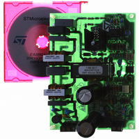
EVL6562A-35WFLB
Description
BOARD EVAL FOR L6562AX
Manufacturer
STMicroelectronics
Type
Power Factor Correctionr
Specifications of EVL6562A-35WFLB
Main Purpose
Power Management, Power Factor Correction
Embedded
No
Utilized Ic / Part
L6562A
Primary Attributes
35W, 48V Out, 90 ~ 265VAC In
Secondary Attributes
Transition Mode
Input Voltage
90 V to 265 V
Output Voltage
48 V
Board Size
120 mm x 82 mm
Product
Power Management Modules
Dimensions
120 mm x 82 mm
Lead Free Status / RoHS Status
Lead free / RoHS Compliant
For Use With/related Products
L6562A
Other names
497-8248
Available stocks
Company
Part Number
Manufacturer
Quantity
Price
Company:

Part Number:
EVL6562A-35WFLB
Manufacturer:
ON
Quantity:
100
Part Number:
EVL6562A-35WFLB
Manufacturer:
ST
Quantity:
20 000


L6562
Table 5. Electrical Characteristics (continued)
(T
(1)
(2)
(3)
4/16
CURRENT SENSE COMPARATOR
V
ZERO CURRENT DETECTOR
STARTER
OUTPUT OVERVOLTAGE
GATE DRIVER
Symbol
V
V
V
I
V
V
I
V
V
I
t
j
CS clamp
V
V
I
t
ZCDsnk
ZCDsrc
ZCDres
CSoffset
I
START
COMP
Oclamp
d(H-L)
ZCDdis
I
V
= -25 to 125°C, V
ZCDb
ZCDen
Hys
V
COMP
GB
ZCDH
I
ZCDL
ZCDA
ZCDT
OVP
G
CS
All parameters are in tracking
The multiplier output is given by:
Parameters guaranteed by design, functionality tested in production.
OH
t
t
OL
f
r
v
Voltage Gain
Gain-Bandwidth Product
Source Current
Sink Current
Upper Clamp Voltage
Lower Clamp Voltage
Input Bias Current
Delay to Outpu
Current sense reference clamp
Current sense offset
Upper Clamp Voltage
Lower Clamp Voltage
Arming Voltage
(positive-going edge)
Triggering Voltage
(negative-going edge)
Input Bias Current
Source Current Capability
Sink Current Capability
Disable threshold
Restart threshold
Restart Current after Disable
Start Timer period
Dynamic OVP triggering current
Hysteresis
Static OVP threshold
Dropout Voltage
Voltage Fall Time
Voltage Rise Time
Output clamp voltage
UVLO saturation
Parameter
CC
t
= 12, C
V
cs
O
=
= 1 nF; unless otherwise specified)
K V
⋅
MUL T
Open loop
V
V
I
I
V
V
V
V
I
I
(3)
(3)
V
(3)
(1)
I
I
I
I
V
⋅
SOURCE
SINK
ZCD
ZCD
GDsource
GDsource
GDsink
GDsource
(
COMP
COMP
CS
COMP
MULT
MULT
ZCD
CC
V
CO MP
= 0
= 0 to V
= 2.5 mA
= -2.5 mA
= 0.5 mA
= 1 to 4.5 V
= 0
= 2.5V
= 200 mA
= 4V, V
= 4V, V
= Upper clamp
= 0.5 mA
–
= 20 mA
= 200 mA
= 5mA; Vcc = 20V
Test Condition
2.5
CCon
)
INV
INV
(1)
, I
= 2.4 V
= 2.6 V
sink
=10mA
Min.
-2.5
150
2.5
5.3
2.1
1.6
5.0
0.3
2.5
2.1
60
30
75
35
10
-2
Typ.
2.25
0.65
2.25
-3.5
200
200
130
4.5
5.7
1.7
5.7
2.1
1.6
2.5
0.9
80
30
75
40
30
30
40
12
1
5
2
2
Max.
-5.5
350
250
350
300
2.4
1.8
6.5
2.4
2.6
1.9
1.1
45
70
80
15
-5
-1
6
1
3
MHz
Unit
mA
mA
mV
mA
mA
mV
mV
dB
µA
µA
µA
µA
µA
ns
µs
ns
ns
V
V
V
V
V
V
V
V
V
V
V
V
Related parts for EVL6562A-35WFLB
Image
Part Number
Description
Manufacturer
Datasheet
Request
R

Part Number:
Description:
BOARD EVAL FOR L6562AX
Manufacturer:
STMicroelectronics
Datasheet:

Part Number:
Description:
BOARD EVAL FOR L6562A
Manufacturer:
STMicroelectronics
Datasheet:

Part Number:
Description:
EVALUATION MODULE L6562A
Manufacturer:
STMicroelectronics
Datasheet:

Part Number:
Description:
STMicroelectronics [RIPPLE-CARRY BINARY COUNTER/DIVIDERS]
Manufacturer:
STMicroelectronics
Datasheet:
Part Number:
Description:
STMicroelectronics [LIQUID-CRYSTAL DISPLAY DRIVERS]
Manufacturer:
STMicroelectronics
Datasheet:

Part Number:
Description:
BOARD EVAL FOR MEMS SENSORS
Manufacturer:
STMicroelectronics
Datasheet:
Part Number:
Description:
NPN TRANSISTOR POWER MODULE
Manufacturer:
STMicroelectronics
Datasheet:
Part Number:
Description:
TURBOSWITCH ULTRA-FAST HIGH VOLTAGE DIODE
Manufacturer:
STMicroelectronics
Datasheet:
Part Number:
Description:
Manufacturer:
STMicroelectronics
Datasheet:
Part Number:
Description:
DIODE / SCR MODULE
Manufacturer:
STMicroelectronics
Datasheet:
Part Number:
Description:
DIODE / SCR MODULE
Manufacturer:
STMicroelectronics
Datasheet:
Part Number:
Description:
Search -----> STE16N100
Manufacturer:
STMicroelectronics
Datasheet: