EVAL6206PD STMicroelectronics, EVAL6206PD Datasheet - Page 9
EVAL6206PD
Manufacturer Part Number
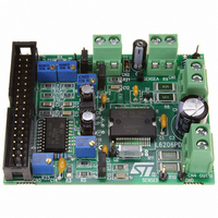
EVAL6206PD
Description
EVAL BOARD FOR L6206 SERIES
Manufacturer
STMicroelectronics
Datasheet
1.L6206N.pdf
(23 pages)
Specifications of EVAL6206PD
Mfg Application Notes
PractiSPIN AppNote
Design Resources
EVAL6206PD/6206PD Gerber Files EVAL6206PD Schematic/Bill of Materials
Main Purpose
Power Management, H Bridge Driver (Internal FET)
Embedded
No
Utilized Ic / Part
L6206
Primary Attributes
2 H-Bridge, 8 ~ 52V Output, Use with PractiSPIN
Secondary Attributes
Temperature Protection, Adjustable Current Limit
Applications
Motor Control
Processor To Be Evaluated
L6206PD
For Use With
497-4138 - EVALUATION BOARD PRACTISPIN
Lead Free Status / RoHS Status
Contains lead / RoHS non-compliant
Other names
497-4135


NON-DISSIPATIVE OVERCURRENT DETECTION AND PROTECTION
In addition to the PWM current control, an overcurrent detection circuit (OCD) is integrated. This circuit can be
used to provides protection against a short circuit to ground or between two phases of the bridge as well as a
roughly regulation of the load current. With this internal over current detection, the external current sense resis-
tor normally used and its associated power dissipation are eliminated. Fig. 7 shows a simplified schematic of
the overcurrent detection circuit for the Bridge A. Bridge B is provided of an analogous circuit.
To implement the over current detection, a sensing element that delivers a small but precise fraction of the out-
put current is implemented with each high side power MOS. Since this current is a small fraction of the output
current there is very little additional power dissipation. This current is compared with an internal reference cur-
rent I
condition. When a fault condition is detected, an internal open drain MOS with a pull down capability of 4mA
connected to OCD pin is turned on. Fig. 8 shows the OCD operation.
This signal can be used to regulate the output current simply by connecting the OCD pin to EN pin and adding
an external R-C as shown in Fig.7. The off time before recovering normal operation can be easily programmed
by means of the accurate thresholds of the logic inputs.
I
Fig. 9 shows the output current protection threshold versus R
The Disable Time t
rate thresholds of the logic inputs. It is affected whether by C
Figure 10. The Delay Time t
only by C
C
be chosen as big as possible according to the maximum tolerable Delay Time and the R
according to the desired Disable Time.
The resistor R
are respectively 100K and 5.6nF that allow obtaining 200 s Disable Time.
REF
EN
is also used for providing immunity to pin EN against fast transient noises. Therefore the value of C
and, therefore, the output current detection threshold are selectable by R
REF
. When the output current reaches the detection threshold Isover the OCD comparator signals a fault
EN
– Isover = 5.6A ±30% at -25°C < T
– Isover =
value. Its magnitude is reported in Figure 11.
EN
should be chosen in the range from 2.2K to 180K . Recommended values for R
DISABLE
22100
--------------- -
R
CL
before recovering normal operation can be easily programmed by means of the accu-
DELAY
±10% at -25°C < T
before turning off the bridge when an overcurrent has been detected depends
j
< 125°C if R
j
< 125°C if 5K
EN
CL
CL
and R
= 0 (PROGCL connected to GND)
value in the range 5k
EN
R
values and its magnitude is reported in
CL
< 40k
CL
value, following the equations:
EN
value should be chosen
to 40k .
EN
EN
and C
L6206
should
9/23
EN
Related parts for EVAL6206PD
Image
Part Number
Description
Manufacturer
Datasheet
Request
R

Part Number:
Description:
ENERCHIP CC EVAL KIT
Manufacturer:
Cymbet Corporation
Datasheet:

Part Number:
Description:
BOARD EVAL FOR AD976
Manufacturer:
Analog Devices Inc
Datasheet:

Part Number:
Description:
BOARD EVAL FOR ADXL345
Manufacturer:
Analog Devices Inc
Datasheet:

Part Number:
Description:
ENERCHIP CC SEH EVAL KIT
Manufacturer:
Cymbet Corporation
Datasheet:

Part Number:
Description:
ENERCHIP EP ENERGY HARVEST EVAL
Manufacturer:
Cymbet Corporation
Datasheet:

Part Number:
Description:
EVAL BOARD FOR TW6864-LB2-GR
Manufacturer:
Intersil
Datasheet:
Part Number:
Description:
EVAL BOARD FOR TW8816-LB3-GR
Manufacturer:
Intersil
Datasheet:
Part Number:
Description:
EVAL BOARD FOR TW8817-TA3-GRS
Manufacturer:
Intersil
Datasheet:

Part Number:
Description:
EVALUATION MODULE FOR ADUM4160
Manufacturer:
Analog Devices Inc
Datasheet:

Part Number:
Description:
BOARD EVALUATION ADCMP581BCP
Manufacturer:
Analog Devices Inc
Datasheet:
Part Number:
Description:
BOARD EVALUATION ADM1041
Manufacturer:
Analog Devices Inc
Datasheet:

Part Number:
Description:
EVAL BOARD FOR STM32F107VCT
Manufacturer:
STMicroelectronics
Datasheet:
Part Number:
Description:
BOARD EVAL FOR AD1954
Manufacturer:
Analog Devices Inc
Datasheet:
Part Number:
Description:
BOARD EVAL FOR AD1955
Manufacturer:
Analog Devices Inc
Datasheet:

Part Number:
Description:
BOARD EVAL FOR AD7655
Manufacturer:
Analog Devices Inc
Datasheet: