CDB3310 Cirrus Logic Inc, CDB3310 Datasheet - Page 6
CDB3310
Manufacturer Part Number
CDB3310
Description
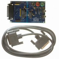
BOARD EVAL FOR CS3310 COL CTRL
Manufacturer
Cirrus Logic Inc
Datasheet
1.CS3310-KSZ.pdf
(17 pages)
Specifications of CDB3310
Main Purpose
Audio, Volume Control
Embedded
No
Utilized Ic / Part
CS3310
Primary Attributes
Stereo Volume Control, 0.5 dB Step Size, Serial Control
Secondary Attributes
-95.5 dB Attenuation, +31.5 dB Gain, 0.001% THD+N, 116 dB Dynamic Range
Product
Audio Modules
Lead Free Status / RoHS Status
Contains lead / RoHS non-compliant
Lead Free Status / RoHS Status
Lead free / RoHS Compliant, Contains lead / RoHS non-compliant
Other names
598-1000


CS3310
GENERAL DESCRIPTION
The CS3310 is a stereo, digital volume control designed for audio systems. The levels of the left
and right analog input channels are set by a 16-bit serial data word; the first 8 bits address the
right channel and the remaining 8 bits address the left channel, as detailed in Table 1. Resistor
values are decoded to 0.5 dB resolution by an internal multiplexer for a total attenuation range of
-95.5 dB. An output amplifier stage provides a programmable gain of up to 31.5 dB in 0.5 dB
steps. This results in an overall 8-bit adjustable range of 127 dB.
The CS3310 operates from ±5 V supplies and accepts inputs up to ±3.75 V. Once in operation,
the CS3310 can be brought to a muted state with the mute pin, MUTE, or by writing all zeros to
the volume control registers. The device contains a simple three wire serial interface which ac-
cepts 16-bit data. This interface also supports daisy-chaining capability.
SYSTEM DESIGN
Very few external components are required to support the CS3310. Normal power supply decou-
pling components are all that is required, as shown in Figure 2.
Serial Data Interface
The CS3310 has a simple, three wire interface that consists of three input pins: SDATAI, serial
data input; SCLK, serial data clock and CS, the chip select input. SDATAO, serial data output,
enables the user to read the current volume setting or provide daisy-chaining of multiple
CS3310’s.
The 16-bit serial data is formatted MSB first and clocked into SDATAI by the rising edge of SCLK
with CS low as shown in Figure 3. The data is latched by the rising edge of CS and the analog
output levels of both left and right channels are set. The existing data in the volume control data
register is clocked out SDATAO on the falling edge of SCLK. This data can be used to read cur-
rent gain/attenuation levels or to daisy chain multiple CS3310’s. See Figure 1 for proper setup
and hold times for CS, SDATAI, SCLK, and SDATAO. SCLK and SDATAI should be active only
during volume setting operations to achieve optimum dynamic range.
Daisy Chaining
Digitally controlled, multi-channel audio systems often result in complex address decoding which
complicates PCB layout. This is greatly simplified with the daisy-chaining capability of the
CS3310.
6
DS82F1
Related parts for CDB3310
Image
Part Number
Description
Manufacturer
Datasheet
Request
R

Part Number:
Description:
Development Kit
Manufacturer:
Cirrus Logic Inc
Datasheet:
Part Number:
Description:
Development Kit
Manufacturer:
Cirrus Logic Inc
Datasheet:


Part Number:
Description:
High-efficiency PFC + Fluorescent Lamp Driver Reference Design
Manufacturer:
Cirrus Logic Inc
Datasheet:
Part Number:
Description:
Development Kit
Manufacturer:
Cirrus Logic Inc
Datasheet:
Part Number:
Description:
Development Kit
Manufacturer:
Cirrus Logic Inc
Datasheet:

Part Number:
Description:
Development Kit
Manufacturer:
Cirrus Logic Inc
Datasheet:
Part Number:
Description:
Development Kit
Manufacturer:
Cirrus Logic Inc
Datasheet:
Part Number:
Description:
Development Kit
Manufacturer:
Cirrus Logic Inc
Datasheet:
Part Number:
Description:
Development Kit
Manufacturer:
Cirrus Logic Inc
Datasheet:

Part Number:
Description:
EVALUATION BOARD FOR CS8427
Manufacturer:
Cirrus Logic Inc
Datasheet:

Part Number:
Description:
BOARD EVAL FOR CS8416 RCVR
Manufacturer:
Cirrus Logic Inc
Datasheet:

Part Number:
Description:
EVALUATION BOARD FOR CS8420
Manufacturer:
Cirrus Logic Inc
Datasheet:

Part Number:
Description:
KIT DEVELOPMENT EP9315 ARM9
Manufacturer:
Cirrus Logic Inc
Datasheet:

Part Number:
Description:
KIT DEVELOPMENT EP9302 ARM9
Manufacturer:
Cirrus Logic Inc
Datasheet: