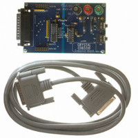
CDB3310 Cirrus Logic Inc, CDB3310 Datasheet

CDB3310
Specifications of CDB3310
Related parts for CDB3310
CDB3310 Summary of contents
Page 1
Stereo Digital Volume Control Features Complete Digital Volume Control — 2 Independent Channels — Serial Control — 0.5 dB Step Size Wide Adjustable Range — -95.5 dB Attenuation — +31.5 dB Gain Low Distortion & Noise — 0.001% THD+N — ...
Page 2
ANALOG CHARACTERISTICS 2 kΩ pF kHz Measurement Bandwidth; unless otherwise specified) L Parameter DC Characteristics Step Size Gain Error (31.5 dB Gain) Gain Matching Between Channels Input Resistance Input Capacitance AC Characteristics Total ...
Page 3
DIGITAL CHARACTERISTICS Parameter High-Level Input Voltage Low-Level Input Voltage High-Level Output Voltage Low-Level Output Voltage Input Leakage Current SWITCHING CHARACTERISTICS Parameter Serial Clock Serial Clock MUTE Input Timing SDATAI Set Up Time SDATAI Hold Time CS Valid to SCLK Rising ...
Page 4
RECOMMENDED OPERATING CONDITIONS Parameter DC Power Supplies: Ambient Operating Temperature Notes: 3. Applying power to VD+ prior to VA+ creates a SCR latch-up condition. Refer to Figure 2 for the recommended power connections. ABSOLUTE MAXIMUM RATINGS Parameter DC Power Supplies: ...
Page 5
F 10 µ F CONTROLLER 16 AUDIO SOURCE *Required to terminate SDATAI due to high impedance state of SDATAO when CS is high. **Refer to Note 3. Figure 2. Recommended Connection Diagram DS82F1 ** ...
Page 6
GENERAL DESCRIPTION The CS3310 is a stereo, digital volume control designed for audio systems. The levels of the left and right analog input channels are set by a 16-bit serial data word; the first 8 bits address the right channel ...
Page 7
CS SCLK SDATAI SDATAO L0 = Left Channel Least Significant Bit L7 = Left Channel Most Significant Bit SDATAI is latched internally on the rising edge of SCLK SDATAO transitions after the falling edge of SCLK SDATAO bits reflect the ...
Page 8
Changing the Analog Output Level Care has been taken to ensure that there are no audible artifacts in the analog output signal dur- ing volume control changes. The gain/attenuation changes of the CS3310 occur at zero cross- ings to eliminate ...
Page 9
Source impedances equal to or less than 600 ohms will avoid this dis- tortion mechanism for the CS3310. Mute Muting can be ...
Page 10
PCB Layout, Grounding and Power Supply Decoupling As with any high performance device which contains both analog and digital circuitry, careful at- tention to power supply and grounding arrangements must be observed to optimize performance. Figure 2 shows the recommended ...
Page 11
Figure 16k FFT plot demonstrating the crosstalk performance of the CS3310 at 20 kHz. Both channels were set to unity gain. The right channel input is grounded with the left channel driven to 2.65 Vrms output at ...
Page 12
THD+N% vs AMPL (Vrms .01 .001 .0001 0.1 Figure 6. THD+N vs. AMP AMPL (dBr) vs FREQ (Hz) 1.0 0.5 0.0 -0.5 -1.0 -1.5 -2.0 10 100 1k Figure 8. Frequency Response Full Scale Input 0.1000 0.0100 ...
Page 13
PIN DESCRIPTION Zero Crossing Enable Chip Select Serial Data Input Positive Digital Power Digital Ground Serial Clock Input Serial Data Output Power Supply Connections VA+ - Positive Analog Power, Pin 12. Positive analog supply. Nominally +5 volts. VA- - Negative ...
Page 14
Analog Inputs and Outputs AINL, AINR - Left and Right Channel Analog Inputs, Pins 16, 9. Analog input connections for the left and right channels. Nominally ±3.75 volts for a full scale input. AOUTL, AOUTR - Left and Right Channel ...
Page 15
ZCEN - Zero Crossing Enable, Pin 1. This pin enables or disables the zero crossing detection and time-out function used during analog output level transitions. A high level on this pin enables the zero crossing detection function. A low level ...
Page 16
PACKAGE DIMENSIONS 16L SOIC (300 MIL BODY) PACKAGE DRAWING 1 b SEATING PLANE e DIM ∝ INCHES MIN MAX 0.093 0.104 0.004 0.012 0.013 0.020 ...
Page 17
Revision Date PP1 April 1991 Initial release PP2 December 1992 Update specifications PP3 February 1999 Update specifications PP4 Update specifications and bring into new template. July 2004 Add lead free part. F1 September 2005 Added “Lead Free” to Ordering Information ...


