ATAVRBC100 Atmel, ATAVRBC100 Datasheet - Page 7
ATAVRBC100
Manufacturer Part Number
ATAVRBC100
Description
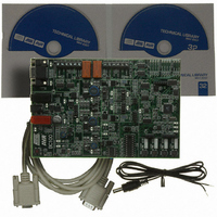
REF DESIGN KIT BATTERY CHARGER
Manufacturer
Atmel
Series
AVR®r
Datasheet
1.ATAVRBC100.pdf
(12 pages)
Specifications of ATAVRBC100
Main Purpose
Power Management, Battery Charger
Embedded
Yes, MCU, 8-Bit
Utilized Ic / Part
ATtiny261/461/861/25/45/85
Primary Attributes
Multi Chemistry, 3 Circuits, (2) 1.2 ~ 20V @ 1A/2.5A Out, (1) 1.2 ~ 38V @ 5A
Secondary Attributes
7.5 ~ 40V In, 2 Relays, Supports Optional DB101 Display Board
Data Bus Width
8 bit
Interface Type
RS-232
Silicon Manufacturer
Atmel
Silicon Core Number
AVR451
Kit Application Type
Power Management - Battery
Application Sub Type
Battery Charger
Silicon Family Name
AVR
Rohs Compliant
Yes
Lead Free Status / RoHS Status
Lead free / RoHS Compliant


4.2 RS232C connector
4.3 Battery terminals
4.4 DB101 headers
8088A-AVR-09/07
A RS232C connector is available to connect the BC100 to e.g. a PC. The RS232C
connector is connected to the ATmega644 board controller (USART0) and can be
used interact with or as a gateway to the ATtiny AVRs connected to the charging
circuits.
The charger can connect to two individual battery packs, which can be connected to
the board through two sets of screw-terminals. Please refer to Figure 2-1 to identify
the battery terminals (Battery A and Battery B).
The battery connectors (J500 and J501) support various types of battery packs.
Therefore, in addition to the positive and negative battery poles, the connector has
additional terminals (see Table 4-1, below).
Table 4-1. Terminals on the battery connectors.
The buck converter outputs are connected to the terminals through relays, to make it
possible to connect two batteries to one charger. The relays are default open (not
conducting), and should therefore be actively closed to connect a battery. The two
relays should not be closed at the same time unless the two batteries are having the
same voltage level. When a relay is closed the corresponding active-LED (D500 and
D501) will light up.
When using an ATtinyx5 to charge a battery, only one battery pack should be
connected (unless the battery packs are meant to be in parallel). Note that the
ATtinyx5 cannot control the relays, due to the lack of available pins, and therefore it is
required to either program the ATtinyx61 to enable the relay(s) or to short pin 7
(battery A enable) / pin 8 (battery B enable) of the ATtinyx61 socket to V3P3A (pin 5).
A DB101 display board can be mounted as a top module on the BC100: The BC100
board controller (ATmega644) can pass information to the DB101 through a serial
link. The information can in this way be presented on the graphical display on the
DB101. Please refer to Figure 2-1 to identify the three DB101 female pin header.
Terminal label
BATTERY+
BATTERY-
RID/NTC
1-WIRE/SDA
SCL
ENABLE
Notes:
(1)
(1)
1. In applications were both NTC and RID are used the SCL terminal can be used
as alternative RID input.
Use
Positive pole of the battery
Negative pole of the battery
For batteries that have either a Resistor ID (RID) or Negative
Temperature Coefficient resistor (NTC) line.
For batteries that have a built-in 1-Wire eeprom (from where
battery parameters can be read).
Alternative, a TWI/SMBus data line can be connected to this line
(for a smart battery charger)
A TWI/SMBus clock line can be connected to this line (for a smart
battery charger)
Can be connected if the battery has an enable line.
AVR451
7
Related parts for ATAVRBC100
Image
Part Number
Description
Manufacturer
Datasheet
Request
R

Part Number:
Description:
DEV KIT FOR AVR/AVR32
Manufacturer:
Atmel
Datasheet:

Part Number:
Description:
INTERVAL AND WIPE/WASH WIPER CONTROL IC WITH DELAY
Manufacturer:
ATMEL Corporation
Datasheet:
Part Number:
Description:
Low-Voltage Voice-Switched IC for Hands-Free Operation
Manufacturer:
ATMEL Corporation
Datasheet:
Part Number:
Description:
MONOLITHIC INTEGRATED FEATUREPHONE CIRCUIT
Manufacturer:
ATMEL Corporation
Datasheet:
Part Number:
Description:
AM-FM Receiver IC U4255BM-M
Manufacturer:
ATMEL Corporation
Datasheet:
Part Number:
Description:
Monolithic Integrated Feature Phone Circuit
Manufacturer:
ATMEL Corporation
Datasheet:
Part Number:
Description:
Multistandard Video-IF and Quasi Parallel Sound Processing
Manufacturer:
ATMEL Corporation
Datasheet:
Part Number:
Description:
High-performance EE PLD
Manufacturer:
ATMEL Corporation
Datasheet:
Part Number:
Description:
8-bit Flash Microcontroller
Manufacturer:
ATMEL Corporation
Datasheet:
Part Number:
Description:
2-Wire Serial EEPROM
Manufacturer:
ATMEL Corporation
Datasheet: