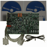
ATAVRBC100 Atmel, ATAVRBC100 Datasheet

ATAVRBC100
Specifications of ATAVRBC100
Related parts for ATAVRBC100
ATAVRBC100 Summary of contents
Page 1
AVR451: BC100 Hardware User's Guide Features • Tripple buck converter for battery charging. - Low voltage/current (max 20V/1A). - Medium voltage/current (max 20V/2.5A). - High voltage/current (max 38V/5A). • Battery (dis)charging using ATtiny261/461/861 or ATtiny25/45/85. - Uses DC supply voltage ...
Page 2
Hardware overview Figure 2-1. Overview of the BC100. DC Power (7.5V-40V) 38V/5A buck converter 30V/2.5A buck converter 20V/1A buck converter ATtinyx5 socket ATtinyx61 socket DataFlash ATmega644 board controller AVR451 2 The BC100 consists of two main parts: the battery ...
Page 3
Main hardware blocks 3.1 Buck converters Figure 3-1. The three buck converters of the BC100 (section of the BC100 schematics). 8088A-AVR-09/07 The blocks of the BC100 used for battery charging are described below. For more details on parts of ...
Page 4
Shunt network Figure 3-2. The shunt resistor and configurable divider network (section of the BC100 schematics). AVR451 4 A shunt resistor (70mOhm, 1%) is placed in the charge/discharge path of the battery. The shunt resistor is used to measure ...
Page 5
Electronic load Figure 3-3. The electronic constant current loads (section of the BC100 schematics). 8088A-AVR-09/07 The maximum input voltages to the ATtiny device must be below the supply voltage of the ATtiny, and the differential voltage over the shunt ...
Page 6
Supply voltages and ground levels 3.5 ADC reference 4 Connectors and jumpers 4.1 Power connector AVR451 6 Always keep the temperature of the FETs (Q404 and Q405) and the resistors (R444 and R445) below a reasonable temperature (very warm ...
Page 7
RS232C connector 4.3 Battery terminals 4.4 DB101 headers 8088A-AVR-09/07 A RS232C connector is available to connect the BC100 to e.g. a PC. The RS232C connector is connected to the ATmega644 board controller (USART0) and can be used interact with ...
Page 8
Programming and debugging headers Figure 4-1. Programming and debugging headers. ATtinyx5 ISP and DebugWire header ATtinyx61 ISP and DebugWire header ATmega644 JTAG header AVR451 8 Note that ATmega644 firmware for communicating with the DB101 is not included in the ...
Page 9
Jumpers overview 8088A-AVR-09/07 ATmega644 board controller it can be programmed regardless of the state of the SPI lines. If SPI communication is used between a ATtiny and the ATmega644 a way to ensure that programming is successful ...
Page 10
Figure 4-2. Location of jumpers on the BC100. J402 J403 J404 J302 J405 4.7 Micro switches and LEDs 4.8 Test points AVR451 10 Designator Use and settings Connects the either “BUCK-A”, BUCK-B” or “BUCK-C” converter output to the battery terminals ...
Page 11
... Preprogrammed firmware 8088A-AVR-09/07 The BC100 comes with the firmware from application note AVR458 “Charging Lithium-Ion Batteries with ATAVRBC100” programmed in the ATtiny861. The ATtiny85, is programmed with a small program that does nothing but putting the device in Power Down mode. The ATmega644 is programmed with a firmware that controls the power switch on the board, but other wise do nothing ...
Page 12
... BEEN ADVISED OF THE POSSIBILITY OF SUCH DAMAGES. Atmel makes no representations or warranties with respect to the accuracy or completeness of the contents of this document and reserves the right to make changes to specifications and product descriptions at any time without notice. Atmel does not make any commitment to update the information contained herein. Unless specifically provided otherwise, Atmel products are not suitable for, and shall not be used in, automotive applications. Atmel’ ...


