DV250501 Microchip Technology, DV250501 Datasheet - Page 31
DV250501
Manufacturer Part Number
DV250501
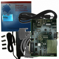
Description
KIT DEV CAN MCP250XX
Manufacturer
Microchip Technology
Type
Network Controller & Processorr
Specifications of DV250501
Main Purpose
Interface, CAN I/O Expander
Embedded
Yes, MCU, 8-Bit
Utilized Ic / Part
MCP25020, MCP25050
Primary Attributes
V2.0B up to 1Mb/s Data Rate
Data Rate
1 Mbps
Interface Type
CAN
Operating Voltage
2.7 V to 5.5 V
Product
Modules
Lead Free Status / RoHS Status
Lead free / RoHS Compliant
Secondary Attributes
-
Lead Free Status / Rohs Status
Lead free / RoHS Compliant
Other names
Q1221418
Available stocks
Company
Part Number
Manufacturer
Quantity
Price
Company:

Part Number:
DV250501
Manufacturer:
MICROCHIP
Quantity:
12 000
Part Number:
DV250501
Manufacturer:
MICROCHIP/微芯
Quantity:
20 000


3.4
3.5
2004 Microchip Technology Inc.
ESTABLISHING COMMUNICATION
EXPLAINING THE REGISTER TEMPLATE WINDOWS
3.3.2
If the Select Formatters window is not visible, select it from the View menu. Highlight
(do not uncheck) “Standard Text Format” in the Select Formatters window. Click
Properties and check the desired numeric base (see Figure 2-8).
A few other items must be addressed before proper communication can occur, as
discussed in the next section.
Because the method for establishing communications is exactly the same as the last
chapter, please refer to Section 2.4, “Establishing Communications”.
The Register template provides access to all of the user registers by using the
command messages as defined in the data sheet.
3.5.1
There are three different ways to enter values into the windows, depending on the
window function:
1. Entering byte value in the appropriate box.
2. Clicking up/down counters to increase/decrease the value by one.
3. Double-clicking the desired bit location to toggle the bit to its opposite state.
The register bit names will be displayed for the location directly under the mouse
pointer (Physical Layer and Configuration windows only).
3.5.2
The MCP250XX Filters window allows the user to read, modify and test the mask and
filters settings. Care must be taken when modifying the mask and filter settings, as all,
or partial communications with the MCP250XX may be lost due to improper filter and
mask settings.
Mask and filter settings can be tested against various identifiers simply by entering the
desired identifier in the Test Identifier window and pressing the “Test Buf” button. This
tests the entered identifier with the entered mask and filter settings, indicating pass/fail
for each filter.
Example 3.1: Figure 3-1 shows a test where the mask is configured to accept IDs of
Eh and Fh only (bit 0 = 0 = “don’t care”).
Setting the Numeric Base for Bus Monitor Window
General Information
MCP250XX Filters Window
DS51266C-page 27
Related parts for DV250501
Image
Part Number
Description
Manufacturer
Datasheet
Request
R

Part Number:
Description:
Manufacturer:
Microchip Technology Inc.
Datasheet:
Part Number:
Description:
Manufacturer:
Microchip Technology Inc.
Datasheet:
Part Number:
Description:
Manufacturer:
Microchip Technology Inc.
Datasheet:
Part Number:
Description:
Manufacturer:
Microchip Technology Inc.
Datasheet:
Part Number:
Description:
Manufacturer:
Microchip Technology Inc.
Datasheet:
Part Number:
Description:
Manufacturer:
Microchip Technology Inc.
Datasheet:
Part Number:
Description:
Manufacturer:
Microchip Technology Inc.
Datasheet:
Part Number:
Description:
Manufacturer:
Microchip Technology Inc.
Datasheet: