DV250501 Microchip Technology, DV250501 Datasheet
DV250501
Specifications of DV250501
Available stocks


Related parts for DV250501

DV250501 Summary of contents
Page 1
... Microchip Technology Inc. M MCP250XX Development Kit User’s Guide DS51266C ...
Page 2
... Serialized Quick Turn Programming (SQTP service mark of Microchip Technology Incorporated in the U.S.A. All other trademarks mentioned herein are property of their respective companies. © 2004, Microchip Technology Incorporated, Printed in the U.S.A., All Rights Reserved. Printed on recycled paper. Microchip received ISO/TS-16949:2002 quality system certification for ...
Page 3
... Programming via the ICSP™ Connector ................................................ 34 Chapter 5. Other Capabilities of the Development Board 5.1 Introduction ............................................................................................. 35 5.2 Highlights ................................................................................................ 35 5.3 Oscillator Configurations ........................................................................ 35 5.4 Node A Prototyping Area and Header Pinout ......................................... 36 5.5 External Bus Connections ...................................................................... 37 2004 Microchip Technology Inc. MCP250XX USER’S GUIDE Table of Contents DS51266C-page iii ...
Page 4
... Appendix A. Schematics and Layouts A.1 Introduction ............................................................................................. 39 A.2 V Step-up Regulator ........................................................................... 40 PP A.3 Clock and Data for Programming ........................................................... 41 A.4 PC Node ................................................................................................. 42 A.5 CAN Physical Layer ................................................................................ 43 A.6 Node A and Node B ................................................................................ 44 A.7 Caps Page .............................................................................................. 45 Index ..............................................................................................................................47 Worldwide Sales and Service .....................................................................................48 DS51266C-page iv 2004 Microchip Technology Inc. ...
Page 5
... MCP250XX Development Kit. • Index – cross-reference listing of terms, features and sections of this document. • Worldwide Sales and Service – provides the address, telephone and fax numbers for Microchip Technology Inc. sales and service locations throughout the world. Updates Since Microchip tools are constantly evolving to meet customer needs, some software dialogs and/or tool descriptions may differ from this document ...
Page 6
... Many excellent references exist for this software program and should be consulted for general operation of the Windows TROUBLESHOOTING See the README files for information regarding common problems not addressed in this user’s guide. DS51266C-page 2 ® Manuals ® operating system. 2004 Microchip Technology Inc. ...
Page 7
... Microchip’s development systems software products. Plus, this line provides information on how customers can receive any currently available upgrade kits. The Hot Line numbers are: 1-800-755-2345 for U.S. and most of Canada, and 1-480-792-7302 for the rest of the world. 2004 Microchip Technology Inc. DS51266C-page 3 ...
Page 8
... NOTES: DS51266C-page 4 2004 Microchip Technology Inc. ...
Page 9
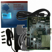
... WHAT IS THE MCP250XX DEVELOPMENT KIT? The MCP250XX Development Kit is an evaluation, demonstration and development tool for Microchip Technology’s 14-pin CAN I/O Expanders. The MCP250XX can be evaluated easily by installing the provided software and running the demonstration program. Furthermore, development can be accomplished by utilizing the bare CAN node with the prototyping area, as well as with the on-board device programmer ...
Page 10
... MCP250XX Development Kit CD-ROM with demo and programming software • Parallel port cable • power supply adapter • Warranty/Registration card • Three MCP25020 CAN I/O Expanders • Three MCP25050 CAN I/O Expanders FIGURE 1-1: DS51266C-page 6 MCP250XX DEVELOPMENT KIT 2004 Microchip Technology Inc. ...
Page 11
... Node bare CAN node next to the prototyping area. This node is used for MCP250XX prototyping and can also be used to program the user defaults via the ICSP protocol. See Figure 1-2 for pinout description. FIGURE 1-2: 2004 Microchip Technology Inc. NODE A PINOUT MCP250XX 1 ...
Page 12
... MCP25050 device. It responds to inputs and CAN messages to demonstrate device functionality. See Figure 1-3 for the pinout description. FIGURE 1-3: LP1 BZ1 DS51266C-page 8 NODE B PINOUT MCP250XX GP0 1 R20 2 GP2 3 4 GP4 5 GP5 6 R17 GP6 2004 Microchip Technology Inc. ...
Page 13
... TABLE 1-1: Key Areas DB25 U6 U15, J5 and JP4 U14 U3 Y1, Y2, Y3, JP1 and JP2 U11, U12, U13, J3 and J4 D2, D3, D4 and D5 CAN traffic indicator LEDs. D2 represents all traffic. D3-D5 represent 2004 Microchip Technology Inc. MCP250XX DEVELOPMENT BOARD DB25 NODE NODE A D2 R17 ...
Page 14
... The DB9 connector, as shown in Figure 1-6, is used to connect the MCP2515 to an external CAN bus and is not necessary for basic board operation. Note: Only the DB9 populated available as needed. FIGURE 1-6: DS51266C-page 10 DB25 PIN CONFIGURATION DB9 CAN CONNECTOR 2004 Microchip Technology Inc. ...
Page 15
... CD-ROM drive). Click OK. Or alternatively, find the CDROM drive using “Windows Explorer” and double click “setup.exe”. Note: Windows NT privileges in order to install the MXLAB 2. Follow the online instructions to install the software. 2004 Microchip Technology Inc. ® and Windows 2000 users must have administrative ® software. DS51266C-page 11 ...
Page 16
... NOTES: DS51266C-page 12 2004 Microchip Technology Inc. ...
Page 17
... Bus Monitor Window (Figure 2-5) – Also known as the “Output” window. This window shows all bus traffic. 6. MCP250XX Demonstration (Figure 2-6) – This window is the graphical interpretation of Node B (the demonstration node). FIGURE 2-1: 2004 Microchip Technology Inc. MCP250XX USER’S GUIDE MENU BAR DS51266C-page 13 ...
Page 18
... FIGURE 2-2: FIGURE 2-3: DS51266C-page 14 PC NODE BIT TIMING AND MODE BOARD STATUS 2004 Microchip Technology Inc. ...
Page 19
... FIGURE 2-4: FIGURE 2-5: 2004 Microchip Technology Inc. MESSAGE FORMAT WINDOW BUS MONITOR WINDOW DS51266C-page 15 ...
Page 20
... FIGURE 2-6: DS51266C-page 16 MCP250XX DEMONSTRATION WINDOW 2004 Microchip Technology Inc. ...
Page 21
... Standard Text Format in the Select Formatters window. Click Properties and check the desired numeric base (see Figure 2-8). A few other items must be addressed before proper communication can occur. These are discussed in the next section. 2004 Microchip Technology Inc. DS51266C-page 17 ...
Page 22
... FIGURE 2-7: FIGURE 2-8: DS51266C-page 18 WARNING ON START-UP CHANGING NUMERIC BASE FOR BUS MONITOR 2004 Microchip Technology Inc. ...
Page 23
... FIGURE 2-9: FIGURE 2-10: 2004 Microchip Technology Inc. OPEN DIALOG TEMPLATE DIALOG DS51266C-page 19 ...
Page 24
... CAN data rate correctly. Open the same window that was opened to set the parallel port address (Figure 2-11). The frequency of oscillation units are displayed in kilohertz (kHz). DS51266C-page 20 PC NODE OPTIONS 2004 Microchip Technology Inc. ...
Page 25
... Highlight (do not uncheck) the “Standard Text Format” option in the Select Formatters window. Click Properties and check the “Delta Times” box. 5. Free-Running Time – A free-running time-stamp between messages with the same identifiers. This mode is activated by unchecking the “Delta Times” box. 2004 Microchip Technology Inc. DS51266C-page 21 ...
Page 26
... Read A/D Regs 0 None 8 Read A/D Regs 0 None Explanation DB0 (address) is either 0x23 or 0x26 (PR1 or PWM2DCH). “Read A/D Regs“ IRM followed by OM. On-bus message. A/D Threshold Detection (R20, POT and PWM2 duty cycle). Command Acknowledge in response to IM. 2004 Microchip Technology Inc. ...
Page 27
... CNF3). 5. MCP250XX Command Messages – Implements the command messages as described in the data sheet. Information Request Messages (IRM), output and input messages are all represented in this window to enable the main functionality of the MCP250XX. 2004 Microchip Technology Inc. MCP250XX USER’S GUIDE DS51266C-page 23 ...
Page 28
... FIGURE 3-1: FIGURE 3-2: DS51266C-page 24 MCP250XX FILTERS MCP250XX ERROR STATES 2004 Microchip Technology Inc. ...
Page 29
... FIGURE 3-3: 2004 Microchip Technology Inc. MCP250XX PHYSICAL LAYER DS51266C-page 25 ...
Page 30
... CAN bus (Figure 2-7). Select “OK, I know what I am doing”. 3. Next, a dialog will appear asking if a new template or a saved project should be opened. Select “New Template” (Figure 2-9). 4. When the template dialog appears, select “MCP250XX Evaluation” (Figure 2-10). DS51266C-page 26 2004 Microchip Technology Inc. ...
Page 31
... Example 3.1: Figure 3-1 shows a test where the mask is configured to accept IDs of Eh and Fh only (bit “don’t care”). 2004 Microchip Technology Inc. DS51266C-page 27 ...
Page 32
... Reading individual registers is actually an IRM that contains the desired register (e.g., reading IOINTEN register is actually a “Read Control Register” IRM command with the resulting output message). Writing an individual register is a “Write Register” input command. DS51266C-page 28 Q 2004 Microchip Technology Inc. ...
Page 33
... MCP250XX Programming Specification (DS20072). The circuitry routes all of the required signals, including the 13V V regulator. Figure 4-1 shows the pinout for the MCP250XX socket in the device programmer circuitry. 2004 Microchip Technology Inc. MCP250XX USER’S GUIDE ® ® IDE with the PRO MATE ...
Page 34
... MCP250XX programming specification. The software has the ability to save user defaults into IHEX8 format, which can be imported to the PRO MATE II device programmer through MPLAB programming the MCP250XX devices. DS51266C-page 30 DEVICE PROGRAMMER DIAGRAM MCP250XX Step-up Regulator Circuit ® IDE for 2004 Microchip Technology Inc. ...
Page 35
... FIGURE 4-2: FIGURE 4-3: 2004 Microchip Technology Inc. PROGRAMMER SOFTWARE MAIN SCREEN USER MEMORY Screen Capture DS51266C-page 31 ...
Page 36
... FIGURE 4-4: FIGURE 4-5: DS51266C-page 32 CAN MODULE PWM MODULES 2004 Microchip Technology Inc. ...
Page 37
... FIGURE 4-6: FIGURE 4-7: 2004 Microchip Technology Inc. A/D MODULE GPIO MODULE DS51266C-page 33 ...
Page 38
... The JP4 jumper allows the MCP250XX socket to be isolated from board power so the programmer does not have to drive the board while programming. FIGURE 4-8: DS51266C-page 34 PROGRAMMING VIA THE ICSP™ CONNECTOR V DD JP4 MCP250XX ICSP™ Connector DATA CLOCK 2004 Microchip Technology Inc. ...
Page 39
... These traces can be cut and jumper pins can be installed to control the oscillator output wiring. See Figure 5-1 for details on the oscillator configurations. FIGURE 5- Node 2004 Microchip Technology Inc. MCP250XX USER’S GUIDE OSCILLATOR SOCKET LAYOUT Y2 Y1 ...
Page 40
... MCP250XX pinout. Figure 5-2 shows the layout of the header. Note: JP4 must be shorted to enable board power to the MCP250XX socket. FIGURE 5-2: DS51266C-page 36 NODE A HEADER LAYOUT Node A Header GP0 GP2 GP4 GP6 TXCAN GP1 GP3 GP5 GP7 RXCAN 2004 Microchip Technology Inc. ...
Page 41
... Pin# Name 1 2 CANL 3 CAN_GND CANH 8 9 CAN_V+ FIGURE 5-3: 2004 Microchip Technology Inc. CAN CONNECTOR PINOUT — Reserved CAN low bus line CAN ground — Reserved N/C Not connected N/C Not connected CAN high bus line — Reserved CAN power ...
Page 42
... NOTES: DS51266C-page 38 2004 Microchip Technology Inc. ...
Page 43
... MCP250XX Development Kit. Diagrams included in this appendix include: • V Step-Up Regulator circuit PP • Programming Clock/Data Logic circuit • PC Interface/CAN Node circuit • CAN Bus Interface circuit • Node A/Node B circuit • Capacitors circuit 2004 Microchip Technology Inc. MCP250XX USER’S GUIDE DS51266C-page 39 ...
Page 44
... A.2 V Step-up Regulator PP FIGURE A-1: V STEP-UP REGULATOR CIRCUIT PP µ µ DS51266C-page 40 100 R2 10K 2.21K R5 23. 6.3 16V - µF 100 R4 {Value} L1 160 R3 10K R8 2004 Microchip Technology Inc. ...
Page 45
... A.3 CLOCK AND DATA FOR PROGRAMMING FIGURE A-2: PROGRAMMING CLOCK/DATA LOGIC CIRCUIT SN74AHCT1G126 SN74AHCT1G126 2004 Microchip Technology Inc MCP25050 DS51266C-page 41 ...
Page 46
... A.4 PC NODE FIGURE A-3: PC INTERFACE/CAN NODE CIRCUIT DS51266C-page 42 2004 Microchip Technology Inc. ...
Page 47
... A.5 CAN PHYSICAL LAYER FIGURE A-4: CAN BUS INTERFACE CIRCUIT 2004 Microchip Technology Inc. DS51266C-page 43 ...
Page 48
... A.6 NODE A AND NODE B FIGURE A-5: NODE A/NODE B CIRCUIT DS51266C-page 44 2004 Microchip Technology Inc. ...
Page 49
... A.7 CAPS PAGE FIGURE A-6: CAPACITORS CIRCUIT µF .1 µ µF .1 µF 2004 Microchip Technology Inc µF .1 µF .1 µF .1 µ µF .1 µF .1 µF .1 µ µF .1 µF .1 µF .1 µF .1 µF 100 pF DS51266C-page 45 ...
Page 50
... NOTES: DS51266C-page 46 2004 Microchip Technology Inc. ...
Page 51
... Key Areas of the Development Board ................ 6 Kit Components .................................................. 6 System Requirements ........................................ 5 Programming the User Defaults: Device Programmer .......................................... 29 PC Software...................................................... 30 Programming via the ICSP™ Connector .......... 34 2004 Microchip Technology Inc. MCP250XX USER’S GUIDE Index R Recommended Reading ............................................ 2 Register Template Windows .................................... 27 Register View Tutorial: Setting the Numeric Base ................................. 27 Setting Up the Evaluation Mode ...
Page 52
... Italy Via Quasimodo, 12 20025 Legnano (MI) Milan, Italy Tel: 39-0331-742611 Fax: 39-0331-466781 Netherlands Biesbosch 14 NL-5152 SC Drunen, Netherlands Tel: 31-416-690399 Fax: 31-416-690340 United Kingdom 505 Eskdale Road Winnersh Triangle Wokingham Berkshire, England RG41 5TU Tel: 44-118-921-5869 Fax: 44-118-921-5820 01/26/04 2004 Microchip Technology Inc. ...