MCP6XXXDM-FLTR Microchip Technology, MCP6XXXDM-FLTR Datasheet - Page 30
MCP6XXXDM-FLTR
Manufacturer Part Number
MCP6XXXDM-FLTR
Description
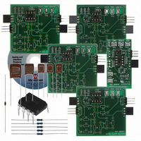
KIT DEMO BOARD ACTIVE FILTER
Manufacturer
Microchip Technology
Datasheet
1.MCP6XXXDM-FLTR.pdf
(46 pages)
Specifications of MCP6XXXDM-FLTR
Main Purpose
Filters, Active - Bandpass, Highpass, Lowpass
Embedded
Yes, MCU, 8-Bit
Utilized Ic / Part
MCP6271
Primary Attributes
Cascadable PCBs, Single Supply
Secondary Attributes
Bessel, Butterworth, and Chebyshev, with Order 1 ~ 8
Processor To Be Evaluated
MCP6271
Lead Free Status / RoHS Status
Not applicable / Not applicable
Lead Free Status / RoHS Status
Lead free / RoHS Compliant, Not applicable / Not applicable
Available stocks
Company
Part Number
Manufacturer
Quantity
Price
Company:

Part Number:
MCP6XXXDM-FLTR
Manufacturer:
MICROCHIP
Quantity:
12 000
Part Number:
MCP6XXXDM-FLTR
Manufacturer:
MICROCHIP/微芯
Quantity:
20 000


DS51614A-page 26
To implement dual supplies, it is also necessary to change the Active Filter Section
(see Figure 4-2) set-up:
• The boards’ bypass capacitors (C1 and C3) need to be removed and replaced
• If desired, R1 and C1 can be removed
• Connect the Oscilloscope as follows
FIGURE 4-2:
Using dual supplies may not work well for high frequency designs. –V
connected to the ground plane, instead of GND, causing greater radiation of supply
noise and more crosstalk.
4.2.2
The total voltage across the power supplies should not exceed the op amp’s
specification (5.5V for the MCP6271). The large bypass capacitors on each board are
rated at 16V, which also limits the possible supply voltage.
If necessary, op amps with higher supply voltage can be accommodated. The boards’
bypass capacitors must be removed and replaced with other bypass capacitors with a
higher voltage rating.
- Connect one set from –VS (board GND) to GND (board VDD/2)
- Connect the other set from +VS (board VDD) to GND (board VDD/2).
- Oscilloscope signal probe to VOUT (TP1)
- Oscilloscope GND probe to VDD/2 (TP3)
Note:
V
GND
GND
GND
DD
V
V
DD
/2
IN
Increased Power Supply Voltages
Do not connect the oscilloscope GND probe to board GND (TP2) when set
up for dual supplies; this may cause a ground conflict between lab
equipment.
Setting up Active Filter Section” or dual supplies.
ground probe to GND
Do not connect
V
Oscilloscope
OUT
© 2006 Microchip Technology Inc.
GND
S
will be
V
V
GND
GND
V
GND
DD
DD
OUT
/2
Related parts for MCP6XXXDM-FLTR
Image
Part Number
Description
Manufacturer
Datasheet
Request
R

Part Number:
Description:
Manufacturer:
Microchip Technology Inc.
Datasheet:
Part Number:
Description:
Manufacturer:
Microchip Technology Inc.
Datasheet:
Part Number:
Description:
Manufacturer:
Microchip Technology Inc.
Datasheet:
Part Number:
Description:
Manufacturer:
Microchip Technology Inc.
Datasheet:
Part Number:
Description:
Manufacturer:
Microchip Technology Inc.
Datasheet:
Part Number:
Description:
Manufacturer:
Microchip Technology Inc.
Datasheet:
Part Number:
Description:
Manufacturer:
Microchip Technology Inc.
Datasheet:
Part Number:
Description:
Manufacturer:
Microchip Technology Inc.
Datasheet: