MCP6XXXDM-FLTR Microchip Technology, MCP6XXXDM-FLTR Datasheet - Page 25
MCP6XXXDM-FLTR
Manufacturer Part Number
MCP6XXXDM-FLTR
Description
KIT DEMO BOARD ACTIVE FILTER
Manufacturer
Microchip Technology
Datasheet
1.MCP6XXXDM-FLTR.pdf
(46 pages)
Specifications of MCP6XXXDM-FLTR
Main Purpose
Filters, Active - Bandpass, Highpass, Lowpass
Embedded
Yes, MCU, 8-Bit
Utilized Ic / Part
MCP6271
Primary Attributes
Cascadable PCBs, Single Supply
Secondary Attributes
Bessel, Butterworth, and Chebyshev, with Order 1 ~ 8
Processor To Be Evaluated
MCP6271
Lead Free Status / RoHS Status
Not applicable / Not applicable
Lead Free Status / RoHS Status
Lead free / RoHS Compliant, Not applicable / Not applicable
Available stocks
Company
Part Number
Manufacturer
Quantity
Price
Company:

Part Number:
MCP6XXXDM-FLTR
Manufacturer:
MICROCHIP
Quantity:
12 000
Part Number:
MCP6XXXDM-FLTR
Manufacturer:
MICROCHIP/微芯
Quantity:
20 000


3.4
© 2006 Microchip Technology Inc.
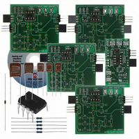
TESTING THE FILTER
Figure 3-3 is a picture of the fully assembled filter shown in Figure 3-1. Note that the
board on the left (V
source and power supply to the filter. JP1 on this board may be connected to INT or
EXT in this case.
FIGURE 3-3:
Kit.
3.4.1
Figure 3-4 shows the most important DC bias voltages to check.
FIGURE 3-4:
3.4.2
Resistors and capacitors with tighter tolerances will reduce the variability of the filters
response over process and, sometimes, temperature. Figure 3-5 shows the simulated
±3.3 sigma gain error (in dB) for each frequency (based on a uniform random
distribution). Figure 3-6 shows a histogram of the pass-band frequency (f
same simulation.
V
GND
GND
GND
DD
V
V
DD
/2
IN
DC Bias
Response Variability
DD
Picture of the Filter Supported by the Active Filter Demo Board
Points to check DC Bias.
/2 Filter Section) provides an easy way to connect the input signal
Test V
OUT
Here
Test Supply Voltages Here
DS51614A-page 21
P
) from the
V
V
GND
GND
V
GND
DD
DD
OUT
/2
Related parts for MCP6XXXDM-FLTR
Image
Part Number
Description
Manufacturer
Datasheet
Request
R

Part Number:
Description:
Manufacturer:
Microchip Technology Inc.
Datasheet:
Part Number:
Description:
Manufacturer:
Microchip Technology Inc.
Datasheet:
Part Number:
Description:
Manufacturer:
Microchip Technology Inc.
Datasheet:
Part Number:
Description:
Manufacturer:
Microchip Technology Inc.
Datasheet:
Part Number:
Description:
Manufacturer:
Microchip Technology Inc.
Datasheet:
Part Number:
Description:
Manufacturer:
Microchip Technology Inc.
Datasheet:
Part Number:
Description:
Manufacturer:
Microchip Technology Inc.
Datasheet:
Part Number:
Description:
Manufacturer:
Microchip Technology Inc.
Datasheet: