PBMCUSLK Freescale Semiconductor, PBMCUSLK Datasheet - Page 18
PBMCUSLK
Manufacturer Part Number
PBMCUSLK
Description
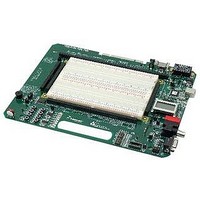
PROJECT BOARD FOR MCU
Manufacturer
Freescale Semiconductor
Datasheet
1.PBMCUSLK.pdf
(30 pages)
Specifications of PBMCUSLK
Module/board Type
Student Learning Kit
Silicon Manufacturer
Freescale
Core Architecture
HCS08, S12
Core Sub-architecture
HCS08, S12
Silicon Core Number
MC9S08, MC9S12
Silicon Family Name
S08QG, S12D
Rohs Compliant
Yes
For Use With/related Products
HC(S)12(X), HC(S)08, DSP, and ColdFire modules
Lead Free Status / RoHS Status
Lead free / RoHS Compliant


DIP SWITCHES
Each DIP switch is configured for active-high operation. When ON (closed), each switch leg is
individually pulled to VDD through a 100 Ω series, current limit resistor.
pulls each signal line to GND when the switch is OFF (open). Each DIP switch output is routed
to the signal breakout header labeled “USER I/O SW[1..7] located adjacent to the breadboard.
LED’s
The PBMCUSLK provides 8, green LED’s, for use as output indicators.
configured for active-high operation. Each LED is individually driven by an ACT buffer allowing
either 5V or 3.3V input levels. The input level is determined by VDD selection. A 10K ohm
resistor holds each buffer input low to prevent inadvertent LED activation. The LED buffer
driver may be disabled by removing the shunt at LED_EN as illustrated in table 4. LED inputs
are routed to the signal breakout header located adjacent to the breadboard. Four LED’s are
connected directly to the MCU_PORT connector.
below for details.
Table 4: LED_EN Option Header
Keypad
The KEYPAD connector shown in figure 11 supports connection of a passive 12-key or 16-key
keypad. The KEYPAD connector is routed directly to the signal breakout header labeled
KEYPAD located adjacent to the breadboard. No current-limit is provided on this connection
and should be provided by the user if required.
Figure 11: Keypad Connector
18
Shunt
ON
OFF
KEYPAD 8
KEYPAD 7
KEYPAD 6
KEYPAD 5
KEYPAD 4
KEYPAD 3
KEYPAD 2
KEYPAD 1
Effect
Enable LED Output
Disable LED Output
8
7
6
5
4
3
2
1
These signal connect directly to the User I/O signal breakout
connector located below the breadboard.
See the “Connected Features” section
Freescale Semiconductor
A 10k ohm resistor
Each LED is
Related parts for PBMCUSLK
Image
Part Number
Description
Manufacturer
Datasheet
Request
R

Part Number:
Description:
Manufacturer:
Freescale Semiconductor, Inc
Datasheet:
Part Number:
Description:
Manufacturer:
Freescale Semiconductor, Inc
Datasheet:
Part Number:
Description:
Manufacturer:
Freescale Semiconductor, Inc
Datasheet:
Part Number:
Description:
Manufacturer:
Freescale Semiconductor, Inc
Datasheet:
Part Number:
Description:
Manufacturer:
Freescale Semiconductor, Inc
Datasheet:
Part Number:
Description:
Manufacturer:
Freescale Semiconductor, Inc
Datasheet:
Part Number:
Description:
Manufacturer:
Freescale Semiconductor, Inc
Datasheet:
Part Number:
Description:
Manufacturer:
Freescale Semiconductor, Inc
Datasheet:
Part Number:
Description:
Manufacturer:
Freescale Semiconductor, Inc
Datasheet:
Part Number:
Description:
Manufacturer:
Freescale Semiconductor, Inc
Datasheet:
Part Number:
Description:
Manufacturer:
Freescale Semiconductor, Inc
Datasheet:
Part Number:
Description:
Manufacturer:
Freescale Semiconductor, Inc
Datasheet:
Part Number:
Description:
Manufacturer:
Freescale Semiconductor, Inc
Datasheet:
Part Number:
Description:
Manufacturer:
Freescale Semiconductor, Inc
Datasheet:
Part Number:
Description:
Manufacturer:
Freescale Semiconductor, Inc
Datasheet: