PBMCUSLK Freescale Semiconductor, PBMCUSLK Datasheet - Page 12
PBMCUSLK
Manufacturer Part Number
PBMCUSLK
Description
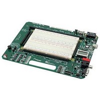
PROJECT BOARD FOR MCU
Manufacturer
Freescale Semiconductor
Datasheet
1.PBMCUSLK.pdf
(30 pages)
Specifications of PBMCUSLK
Module/board Type
Student Learning Kit
Silicon Manufacturer
Freescale
Core Architecture
HCS08, S12
Core Sub-architecture
HCS08, S12
Silicon Core Number
MC9S08, MC9S12
Silicon Family Name
S08QG, S12D
Rohs Compliant
Yes
For Use With/related Products
HC(S)12(X), HC(S)08, DSP, and ColdFire modules
Lead Free Status / RoHS Status
Lead free / RoHS Compliant


MCU Module Power
The PBMCUSLK may optionally power modules attached to the MCU_PORT connectors.
Two, 2-pin jumpers MODULE_POWER VDD(JP4A) and GND(JP4B) enable or disable power
and ground to the MCU_PORT pins as illustrated in figure 3. Installing shunts at positions
labeled VDD and GND connects MCU_PORT, pin 1 to VDD and MCU_PORT, pin 3 to GND.
Figure 3: MOD_PWR Option Header
Integrated USB BDM
The PBMCUSLK board features an integrated USB Background Debug Mode (BDM) from
P&E Microcomputer Systems. The integrated BDM possesses all the necessary signals to
support application development and debugging.
connection from the target board to the host PC. Communication and control signals (BGND,
RESET*) are connected directly to the MCU_PORT connections. This arrangement allows the
user to program and debug Freescale HCS08 and HCS12 Application Modules Student
Learning kits without the need for external wiring.
The integrated USB BDM provides 5V power and ground to the target board eliminating the
need to power the board through VIN or J1. Power provided by the integrated BDM is derived
from the USB bus. Total current consumption for the project board, and connected circuitry,
must not exceed 500mA. This is the current supplied by the USB cable to the BDM, target
board, and any connected circuitry. Excessive current drain will violate the USB specification
causing the USB bus to shutdown.
12
When using this option selection make sure the module connected to the MCU_PORT is not
To complete the circuit, both shunts must be installed. If not used, both shunts should be
configured to source voltage to the project board. Damage to both the project board and
JP4A
●
●
JP4B
●
●
VDD
GND
attached module may result.
Placing a shunt on JP4A routes VDD to MCU_PORT-1.
Placing a shunt on JP4B routes GDN to MCU_PORT-3
CAUTION
removed.
NOTE
A USB type B connector provides
Freescale Semiconductor
Related parts for PBMCUSLK
Image
Part Number
Description
Manufacturer
Datasheet
Request
R

Part Number:
Description:
Manufacturer:
Freescale Semiconductor, Inc
Datasheet:
Part Number:
Description:
Manufacturer:
Freescale Semiconductor, Inc
Datasheet:
Part Number:
Description:
Manufacturer:
Freescale Semiconductor, Inc
Datasheet:
Part Number:
Description:
Manufacturer:
Freescale Semiconductor, Inc
Datasheet:
Part Number:
Description:
Manufacturer:
Freescale Semiconductor, Inc
Datasheet:
Part Number:
Description:
Manufacturer:
Freescale Semiconductor, Inc
Datasheet:
Part Number:
Description:
Manufacturer:
Freescale Semiconductor, Inc
Datasheet:
Part Number:
Description:
Manufacturer:
Freescale Semiconductor, Inc
Datasheet:
Part Number:
Description:
Manufacturer:
Freescale Semiconductor, Inc
Datasheet:
Part Number:
Description:
Manufacturer:
Freescale Semiconductor, Inc
Datasheet:
Part Number:
Description:
Manufacturer:
Freescale Semiconductor, Inc
Datasheet:
Part Number:
Description:
Manufacturer:
Freescale Semiconductor, Inc
Datasheet:
Part Number:
Description:
Manufacturer:
Freescale Semiconductor, Inc
Datasheet:
Part Number:
Description:
Manufacturer:
Freescale Semiconductor, Inc
Datasheet:
Part Number:
Description:
Manufacturer:
Freescale Semiconductor, Inc
Datasheet: