DC9S08QE8 Freescale Semiconductor, DC9S08QE8 Datasheet - Page 20
DC9S08QE8
Manufacturer Part Number
DC9S08QE8
Description
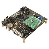
DAUGHTER CARD FOR DEMO9S08QB8
Manufacturer
Freescale Semiconductor
Datasheet
1.DC9S08QB8.pdf
(45 pages)
Specifications of DC9S08QE8
Accessory Type
Daughter Card
Silicon Manufacturer
Freescale
Core Architecture
HCS08
Core Sub-architecture
HCS08
Silicon Core Number
MC9S08
Silicon Family Name
Flexis - S08QE
Kit Contents
Board
Features
Four 8x2 Female Connectors
Rohs Compliant
Yes
For Use With/related Products
DEMO9S
Lead Free Status / RoHS Status
Lead free / RoHS Compliant


16
This PC-based application is used to display the logic analyzer data on the
PC. The logic analyzer data is displayed in real-time and each waveform may
be paused, zoomed, and printed.
If the microcontroller-based Quick Start Application is programmed into the
MCU, the IN0 channel will show the emulated PTC0 signal to have the same
output as the PWM signal at port PTB5 (driving the Buzzer). The IN1 channel
will show the PWM period waveform on channel PTC1.
Step 1.
Step 2.
Step 3.
Step 4.
This PC-based application is included on the DVD-ROM that accompanies
the DEMOQE, and may also be found at:
http://www.pemicro.com/fixedlinks/demoQEtoolkit.html.
Press the button labeled “PTA2.” The PTC0 pin will output a fixed
75% duty cycle pulse width modulation (PWM) signal. The Buzzer
sound is also turned on.
Press the PTA2 button a second time. The PTC0 PWM duty cycle
will change to 25%. The Buzzer remains on.
Press the PTA2 button a third time. The duty cycle is controlled by
the potentiometer (W1). The illumination of LED PTC0 and the
tone of the Buzzer will vary as you rotate the potentiometer.
Press PTA2 a fourth time, or press button PTA3 at any time, to turn
off the Buzzer and all LEDs.
Figure 5-1: Logic Analyzer Application
DEMO9S08QB8 User Manual
Related parts for DC9S08QE8
Image
Part Number
Description
Manufacturer
Datasheet
Request
R

Part Number:
Description:
Manufacturer:
Freescale Semiconductor, Inc
Datasheet:
Part Number:
Description:
Manufacturer:
Freescale Semiconductor, Inc
Datasheet:
Part Number:
Description:
Manufacturer:
Freescale Semiconductor, Inc
Datasheet:
Part Number:
Description:
Manufacturer:
Freescale Semiconductor, Inc
Datasheet:
Part Number:
Description:
Manufacturer:
Freescale Semiconductor, Inc
Datasheet:
Part Number:
Description:
Manufacturer:
Freescale Semiconductor, Inc
Datasheet:
Part Number:
Description:
Manufacturer:
Freescale Semiconductor, Inc
Datasheet:
Part Number:
Description:
Manufacturer:
Freescale Semiconductor, Inc
Datasheet:
Part Number:
Description:
Manufacturer:
Freescale Semiconductor, Inc
Datasheet:
Part Number:
Description:
Manufacturer:
Freescale Semiconductor, Inc
Datasheet:
Part Number:
Description:
Manufacturer:
Freescale Semiconductor, Inc
Datasheet:
Part Number:
Description:
Manufacturer:
Freescale Semiconductor, Inc
Datasheet:
Part Number:
Description:
Manufacturer:
Freescale Semiconductor, Inc
Datasheet:
Part Number:
Description:
Manufacturer:
Freescale Semiconductor, Inc
Datasheet:
Part Number:
Description:
Manufacturer:
Freescale Semiconductor, Inc
Datasheet: