AC002023 Microchip Technology, AC002023 Datasheet - Page 24
AC002023
Manufacturer Part Number
AC002023
Description
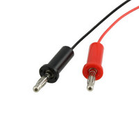
CURRENT MEASUREMENT CABLE
Manufacturer
Microchip Technology
Datasheet
1.PIC24FJ64GA104-IPT.pdf
(36 pages)
Specifications of AC002023
Accessory Type
Measurement Cable
Processor To Be Evaluated
PIC Family
Processor Series
PICxxFIxxx
Lead Free Status / RoHS Status
Lead free / RoHS Compliant
For Use With/related Products
XLP Development Boards
Lead Free Status / Rohs Status
Lead free / RoHS Compliant
For Use With
XLP Development Boards
Lead Free Status / RoHS Status
Lead free / RoHS Compliant, Lead free / RoHS Compliant
Available stocks
Company
Part Number
Manufacturer
Quantity
Price
Company:

Part Number:
AC002023
Manufacturer:
Microchip Technology
Quantity:
135
Company:
Part Number:
AC002023
Manufacturer:
MICROCHIP
Quantity:
12 000


DS51873B-page 24
3.2.4
A bank of jumpers is available to selectively enable various board components. These
jumpers, located in the “Power Control” block on the board, permit the user to perform
customized power management analysis and configure the board more closely to the
user’s application. By removing the jumper for a component, power is disconnected to
the designated IC and supporting circuitry, eliminating power consumption to these
components. See Section 3.3.2 “Component Power Measurement” for more
information on power monitoring.
When the IC PWR switch is set to the “RB2” position, the component select jumpers
determine which components are under software control. Any component not selected
by its corresponding jumper remains disabled.
Component select jumpers are implemented for:
• Serial EEPROM (JP2)
• Modular expansion header (JP6)
• MCP9700 thermistor (JP1)
• ADC/HLVD potentiometer (JP3)
An additional jumper (JP7) selects power for the unpopulated RS-232 serial circuitry.
See Section 3.2.14 “RS-232 Serial Port Options” for more information.
3.2.5
The MCLR switch (S1) is an active-low switch with a pull-up. It resets the PIC24F
microcontroller in either socket. It does not reset the PIC18F14K50 microcontroller
used for USB communication. Therefore, USB communication is not affected by this
switch.
3.2.6
Three capacitive touch pads, based on the Charge Time Measurement Unit (CTMU),
are available. They are multiplexed to three separate analog channels (Table 3-4).
In many capacitive touch applications, an overlay is used to protect the PCB. Mounting
holes are provided to secure overlay materials for evaluation.
The low pin count devices, supported by the XLP 16-bit board, require that the touch
pads be multiplexed with other board components. Specifically, CT2 is multiplexed with
the temperature sensor circuitry, while CT3 is shared with the “Cap Sense” socket with
the C3 designator. To avoid interference with the pads, observe the modifications noted
in Table 3-4.
TABLE 3-4:
Cap Touch Button
Component Select Jumpers
Master Clear Reset (MCLR) Switch
Capacitive Touch Pads
1
2
3
CAPACITIVE TOUCH PAD ANALOG INPUT ASSIGNMENTS
Analog Input
AN5
AN1
AN0
Remove JP5
Unpopulate C3 socket
2010 Microchip Technology Inc.
Note
Related parts for AC002023
Image
Part Number
Description
Manufacturer
Datasheet
Request
R

Part Number:
Description:
Manufacturer:
Microchip Technology Inc.
Datasheet:
Part Number:
Description:
Manufacturer:
Microchip Technology Inc.
Datasheet:
Part Number:
Description:
Manufacturer:
Microchip Technology Inc.
Datasheet:
Part Number:
Description:
Manufacturer:
Microchip Technology Inc.
Datasheet:
Part Number:
Description:
Manufacturer:
Microchip Technology Inc.
Datasheet:
Part Number:
Description:
Manufacturer:
Microchip Technology Inc.
Datasheet:
Part Number:
Description:
Manufacturer:
Microchip Technology Inc.
Datasheet:
Part Number:
Description:
Manufacturer:
Microchip Technology Inc.
Datasheet: