AC002023 Microchip Technology, AC002023 Datasheet - Page 17
AC002023
Manufacturer Part Number
AC002023
Description
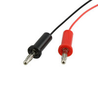
CURRENT MEASUREMENT CABLE
Manufacturer
Microchip Technology
Datasheet
1.PIC24FJ64GA104-IPT.pdf
(36 pages)
Specifications of AC002023
Accessory Type
Measurement Cable
Processor To Be Evaluated
PIC Family
Processor Series
PICxxFIxxx
Lead Free Status / RoHS Status
Lead free / RoHS Compliant
For Use With/related Products
XLP Development Boards
Lead Free Status / Rohs Status
Lead free / RoHS Compliant
For Use With
XLP Development Boards
Lead Free Status / RoHS Status
Lead free / RoHS Compliant, Lead free / RoHS Compliant
Available stocks
Company
Part Number
Manufacturer
Quantity
Price
Company:

Part Number:
AC002023
Manufacturer:
Microchip Technology
Quantity:
135
Company:
Part Number:
AC002023
Manufacturer:
MICROCHIP
Quantity:
12 000


2.2
2010 Microchip Technology Inc.
DEMONSTRATION PROGRAM OPERATION
The demonstration program uses the on-board RS-232 to USB converter to send
system status data in serial form to a standard serial terminal (Figure 2-2). It permits
the user to select which sensor information is displayed and to choose the micro-
controller’s Low-Power mode. This permits users to experiment with various low-power
and XLP techniques, as well as make direct measurements.The program flow is shown
in Figure 2-3.
FIGURE 2-2:
On power-up, the PIC24F16KA102 device will wake-up every 10 seconds from a
Real-Time Clock Calendar (RTCC) interrupt, then re-enter Sleep mode. While awake,
the microcontroller takes a temperature measurement using the MCP9700 tempera-
ture sensor and writes the information to the serial EEPROM. Status information is
displayed, including the wake-up source, Low-Power mode, selected sensor, data
EEPROM information and current temperature. In the default POR configuration, the
RTCC interrupt is the wake-up source, while the MCP9700 is the active sensor.
Push button switches, S2 and S3, can perform multiple functions depending on the
code configuration and how long they are depressed. To minimize power, these
switches use internal pull-ups which are disabled in software when not in use.
Pressing S2 forces a sample to be taken immediately on the selected sensor. This
information is displayed on the terminal window.
Pressing S3 disables the output to the screen. This permits power measurements with-
out the additional current consumed by the UART. Pressing S3 again enables the
UART and permits information to be displayed again.
Pressing and holding S2 for more than two seconds selects the sensor input. Repeated
presses cycle between the temperature sensor, potentiometer, capacitive touch pads
and all three sensors at once. The display reflects each new sensor selection. When
the potentiometer is selected, both V
When the touch pads are selected, their real-time status is displayed. When all three
sources are active at once, all of the sensor information is displayed at one time.
SERIAL TERMINAL DISPLAY FOR THE DEMONSTRATION
APPLICATION
DD
and current potentiometer voltages are shown.
DS51873B-page 17
Related parts for AC002023
Image
Part Number
Description
Manufacturer
Datasheet
Request
R

Part Number:
Description:
Manufacturer:
Microchip Technology Inc.
Datasheet:
Part Number:
Description:
Manufacturer:
Microchip Technology Inc.
Datasheet:
Part Number:
Description:
Manufacturer:
Microchip Technology Inc.
Datasheet:
Part Number:
Description:
Manufacturer:
Microchip Technology Inc.
Datasheet:
Part Number:
Description:
Manufacturer:
Microchip Technology Inc.
Datasheet:
Part Number:
Description:
Manufacturer:
Microchip Technology Inc.
Datasheet:
Part Number:
Description:
Manufacturer:
Microchip Technology Inc.
Datasheet:
Part Number:
Description:
Manufacturer:
Microchip Technology Inc.
Datasheet: