AC002023 Microchip Technology, AC002023 Datasheet - Page 23
AC002023
Manufacturer Part Number
AC002023
Description
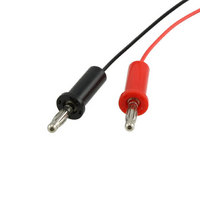
CURRENT MEASUREMENT CABLE
Manufacturer
Microchip Technology
Datasheet
1.PIC24FJ64GA104-IPT.pdf
(36 pages)
Specifications of AC002023
Accessory Type
Measurement Cable
Processor To Be Evaluated
PIC Family
Processor Series
PICxxFIxxx
Lead Free Status / RoHS Status
Lead free / RoHS Compliant
For Use With/related Products
XLP Development Boards
Lead Free Status / Rohs Status
Lead free / RoHS Compliant
For Use With
XLP Development Boards
Lead Free Status / RoHS Status
Lead free / RoHS Compliant, Lead free / RoHS Compliant
Available stocks
Company
Part Number
Manufacturer
Quantity
Price
Company:

Part Number:
AC002023
Manufacturer:
Microchip Technology
Quantity:
135
Company:
Part Number:
AC002023
Manufacturer:
MICROCHIP
Quantity:
12 000


2010 Microchip Technology Inc.
3.2.3.2
The green power LED (D9) illuminates when power is supplied from either the external
9V power supply or the USB connector.
3.2.3.3
The LDO regulator (Q1) is adjustable, and can support a wide voltage range for both
board component and microcontrollers. It can be configured between 1.8V to 5.5V by
changing the values of the voltage divider formed by R28 and R29. Typical values are
listed in Table 3-2. The equation relating the resistor values to target V
Figure A-3 of Section Appendix A. “Development Kit Schematics”. As shipped, the
LDO is configured to supply 3.3V.
The typical drop of the LDO is approximately 1.75V. Ensure the fixed power supply or
USB supply voltage exceeds the desired microcontroller voltage by at least this amount.
The performance of the MCP9700 and the LEDs is diminished at 1.8V operation. If
RS-232 communication is needed at 1.8V, populate the LTC2801 and associated
components. See Section 3.2.14 “RS-232 Serial Port Options” for more information.
TABLE 3-2:
3.2.3.4
The XLP 16-bit board supports multiple regulator configurations for PIC24F devices
with an internal voltage regulator. A slider switch (S4) allows the user to configure the
board for either J-series or K-series Flash devices. With switch, S4, in the “PIC24FJ”
position, the microcontroller’s internal voltage regulator is enabled by connecting a
pull-down resistor to the DISVREG pin and a 10 µF capacitor to the V
For PIC24F J-series devices, additional power savings can be achieved by disabling
the regulator. Three methods are supported by making several component changes to
the “PIC24F VREG” section of the PCB:
• Separate power supply for V
• V
• V
The required component changes are summarized in Table 3-3.
TABLE 3-3:
Split V
Same V
V
Legend: NP = Not Populated; P = Populated
DDCORE
Note:
DDCORE
DDCORE
J-series Regulator
Component
DD
DD
R28
R29
Option
and V
Zener diode
POWER LED
ADJUSTABLE SUPPLY VOLTAGES
ON-CHIP REGULATOR CONFIGURATIONS (PIC24F J-SERIES)
Always verify that the voltage selected on the LDO meets the V
specification of the installed PIC24F device.
and V
and V
connected through a zener diode to V
DDCORE
DDCORE
RESISTOR VALUES FOR R28/R29 VOLTAGE DIVIDER
COMPONENT CHANGES FOR DISABLING ON-CHIP
REGULATOR
DD
connected together
NP
0
NP
R3
150
450
1.8V
DD
and V
R4
NP
Component Placement and Value
DDCORE
1 k
R5
Target V
DD
120
200
3.3V
NP
C4
DD
NP
NP
D6
P
DD
CAP
DS51873B-page 23
is provided in
75
33
5.0V
V
pin.
DD
V
CAP
DDCORE
Point
N/C
N/C
Test
Related parts for AC002023
Image
Part Number
Description
Manufacturer
Datasheet
Request
R

Part Number:
Description:
Manufacturer:
Microchip Technology Inc.
Datasheet:
Part Number:
Description:
Manufacturer:
Microchip Technology Inc.
Datasheet:
Part Number:
Description:
Manufacturer:
Microchip Technology Inc.
Datasheet:
Part Number:
Description:
Manufacturer:
Microchip Technology Inc.
Datasheet:
Part Number:
Description:
Manufacturer:
Microchip Technology Inc.
Datasheet:
Part Number:
Description:
Manufacturer:
Microchip Technology Inc.
Datasheet:
Part Number:
Description:
Manufacturer:
Microchip Technology Inc.
Datasheet:
Part Number:
Description:
Manufacturer:
Microchip Technology Inc.
Datasheet: