20-151-0178 Rabbit Semiconductor, 20-151-0178 Datasheet - Page 24
20-151-0178
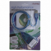
Manufacturer Part Number
20-151-0178
Description
CABLE CONVERTER RS-232 TO USB
Manufacturer
Rabbit Semiconductor
Datasheet
1.20-151-0178.pdf
(162 pages)
Specifications of 20-151-0178
Accessory Type
USB to RS232 Adapter
Product
Microcontroller Accessories
For Use With/related Products
Rabbit-based Boards
Lead Free Status / RoHS Status
Lead free / RoHS Compliant
Other names
20-151-0178
316-1181
316-1181


3.1.2 Board-Specific Information
The PowerCore module and the board to which it is attached are linked by more than their physical con-
nection. Switching the mated core module is not recommended, as the calibration and design numbers are
contained in the core module and will thus no longer match the board.
3.1.2.1 System ID Block
The System ID block is a reserved area in flash memory that contains identification information for the
core module and the design number for the RabbitFLEX BL300F. All RabbitFLEX BL300F devices have
System ID blocks of version 5 or later. The information fields contained in the System ID block are
described in the Rabbit 3000 Designer’s Handbook.
3.1.2.2 User Block
The System ID block has information about the User block. The User block is where calibration constants
are stored. There is memory in the User block for other persistent data that may be required by your appli-
cation.
3.2 Cells and Circuits
The magic of a flex board is the innovative design of the cells, which are abstracted to a level that allows
them to implement one of multiple functions that may be chosen by you, the board designer.
3.2.1 Cell Definition
Cells can be configured or unconfigured. Unconfigured cells are the basic structure unit at the PCB level.
An unconfigured cell can be configured to implement one of several logical functions, thus making it a
configured cell. A configured cell is one in which circuitry has been assembled to form a single function
on a RabbitFLEX board, such as an I/O pin or a serial port.
3.2.2 Cell Descriptions
There are different types of cells available. Each one is designed to handle different types of circuits. Each
I/O pin is supported by a one-transistor or two-transistor cell on the RabbitFLEX BL300F board.
The one- and two-transistor cell layouts pictured in
Figure 3.2
and
Figure 3.3
can be used along with the
board layout pictured in
Figure 3.4
to determine the placement of components on your board. The pad
labels (R2A, R2B, Q1B, etc.) that you see in the cell layout diagrams correspond to the component desig-
nators in the circuit schematics.
For example if you look at the circuit diagram for the 1.4 V trigger threshold digital input, you will see that
the 100 ohm resistor is labeled “R6.” Looking at the one-transistor cell layout, “R6” is located in the
lower-right corner of the cell. The physical placement of “R6” is different when a two-transistor cell is
used to implement the 1.4 V digital input.
www.rabbit.com
18
Design Implementation and Information
Related parts for 20-151-0178
Image
Part Number
Description
Manufacturer
Datasheet
Request
R

Part Number:
Description:
Microcontroller Modules & Accessories Assy Download 1.27MM and 2MM Pitch Cbles
Manufacturer:
Rabbit Semiconductor

Part Number:
Description:
Trimmer Resistors - Multi Turn 20Kohms 5% 1 1/4 PC Mount
Manufacturer:
Bourns Inc.
Datasheet:

Part Number:
Description:
LCD Drivers 160 SEGMENT LCD SEGMENT DRIVER
Manufacturer:
NXP Semiconductors

Part Number:
Description:
20-24 awg TIN PIN REEL M-N-L
Manufacturer:
TE Connectivity
Datasheet:
Part Number:
Description:
IC REAL TIME CLK/CALENDAR 20SOIC
Manufacturer:
NXP Semiconductors
Datasheet:

Part Number:
Description:
IC REAL TIME CLK/CALENDAR 20SOIC
Manufacturer:
NXP Semiconductors
Datasheet:
Part Number:
Description:
IC RTC/CALENDAR TCXO QTZ 20SOIC
Manufacturer:
NXP Semiconductors
Datasheet:

Part Number:
Description:
Manufacturer:
ON Semiconductor
Datasheet:

Part Number:
Description:
20-OUTPUT LVTTL CLOCK DRIVER
Manufacturer:
AMCC (Applied Micro Circuits Corp)
Part Number:
Description:
20-OUTPUT LVTTL CLOCK DRIVER
Manufacturer:
AMCC (Applied Micro Circuits Corp)
Part Number:
Description:
20-OUTPUT CLOCK DRIVER
Manufacturer:
AMCC (Applied Micro Circuits Corp)
