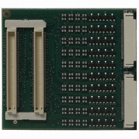
ATICE50PROBE Atmel, ATICE50PROBE Datasheet - Page 43

ATICE50PROBE
Manufacturer Part Number
ATICE50PROBE
Description
PROBE ICE50 W/FLEX CABLES
Manufacturer
Atmel
Datasheet
1.ATICE50MEM.pdf
(73 pages)
Specifications of ATICE50PROBE
Accessory Type
Probe with Flex Cables
For Use With/related Products
AVR ICE 50
Lead Free Status / RoHS Status
Contains lead / RoHS non-compliant
- Current page: 43 of 73
- Download datasheet (2Mb)
5.4
ICE50 User Guide
Fuses and Lock
Bits
The Fuse- and Lock bit settings in the part can be viewed and configured from AVR Stu-
dio. The Fuse settings can only be viewed and not edited in the “Fuse and Lock bit”
view. Configuration is performed in the other views.
In AVR Studio go to Debug->ICE50 options. Highlight Fuses and Lock bits. It is now
possible to view 4 different settings. Note that Fuses marked with “!” do not affect
emulation.
Figure 5-5. Fuse and Lock Bits Settings
1. By pressing “Extended” Fuse the tree expands and it is possible to see the set-
tings for this fuse. “0” indicates on or Fuse programmed, “1” indicates off. It is not
possible to edit the Fuse setting here. The Extended Fuses are available for
selected parts. See the datasheet for the part when configuring the Fuses. In this
case the ATmega128. The Extended Fuse is used to support special features.
See Figure 5-6.
Configuring AVR Studio
2523A–AVR–11/02
5-5
Related parts for ATICE50PROBE
Image
Part Number
Description
Manufacturer
Datasheet
Request
R

Part Number:
Description:
EMULATOR IN CIRCUIT MEGAAVR
Manufacturer:
Atmel
Datasheet:

Part Number:
Description:
DEV KIT FOR AVR/AVR32
Manufacturer:
Atmel
Datasheet:

Part Number:
Description:
INTERVAL AND WIPE/WASH WIPER CONTROL IC WITH DELAY
Manufacturer:
ATMEL Corporation
Datasheet:

Part Number:
Description:
Low-Voltage Voice-Switched IC for Hands-Free Operation
Manufacturer:
ATMEL Corporation
Datasheet:

Part Number:
Description:
MONOLITHIC INTEGRATED FEATUREPHONE CIRCUIT
Manufacturer:
ATMEL Corporation
Datasheet:

Part Number:
Description:
AM-FM Receiver IC U4255BM-M
Manufacturer:
ATMEL Corporation
Datasheet:

Part Number:
Description:
Monolithic Integrated Feature Phone Circuit
Manufacturer:
ATMEL Corporation
Datasheet:

Part Number:
Description:
Multistandard Video-IF and Quasi Parallel Sound Processing
Manufacturer:
ATMEL Corporation
Datasheet:

Part Number:
Description:
High-performance EE PLD
Manufacturer:
ATMEL Corporation
Datasheet:

Part Number:
Description:
8-bit Flash Microcontroller
Manufacturer:
ATMEL Corporation
Datasheet:

Part Number:
Description:
2-Wire Serial EEPROM
Manufacturer:
ATMEL Corporation
Datasheet:


