FPS100048 TDK Corporation, FPS100048 Datasheet - Page 36
FPS100048
Manufacturer Part Number
FPS100048
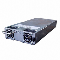
Description
PWR SUP FNT END 48V 1008W 21A
Manufacturer
TDK Corporation
Series
FPSr
Type
Commercialr
Datasheets
1.FPS100024.pdf
(57 pages)
2.FPS100024.pdf
(2 pages)
3.FPS100024.pdf
(1 pages)
4.FPS100048.pdf
(3 pages)
5.FPS100048.pdf
(4 pages)
Specifications of FPS100048
Power Supply Type
Switching (Closed Frame)
Voltage - Output
48V
Number Of Outputs
1
Power (watts)
1000W
Applications
Commercial
Voltage - Input
85 ~ 265VAC
Mounting Type
Chassis Mount
1st Output
48 VDC @ 21A
Size / Dimension
1.61" L x 5" W x 11.4" H (40.9mm x 127mm x 289.6mm)
Power (watts) - Rated
1008W
Operating Temperature
0°C ~ 70°C
Efficiency
88%
Approvals
CE, EN, UL
Line Regulation
0.4%
Load Regulation
0.8%
Power Supply Output Type
Fixed
No. Of Outputs
1
Output Voltage
48V
Output Current
21A
Power Rating
1kW
Input Voltage
85V AC To 265V AC / 120V DC To 360V DC
Maximum Output Current
21 A
Maximum Output Power
1008 W
Input Frequency
47 to 63 Hz
Brand/series
FPS1000 Series
Configuration
Enclosed
Operation
Linear
Output
48 VDC @ 21 A
Power, Output
1008 W
Primary Type
AC-DC
Special Features
High Efficiency, Hot Swappable, PFC, Remote On/Off, Remote Sense
Voltage, Input
85 to 265/120 to 360 VAC/VDC
Voltage, Output
48 VDC
Output Current (max)
21A
Screening Level
Commercial
Product Depth (mm)
127mm
Operating Temperature Min Deg. C
0C
Operating Temperature Max Deg. C
70C
Mounting Style
Screw
Lead Free Status / RoHS Status
Lead free / RoHS Compliant
3rd Output
-
2nd Output
-
4th Output
-
Lead Free Status / Rohs Status
RoHS Compliant part
Other names
285-1239
Available stocks
Company
Part Number
Manufacturer
Quantity
Price
Company:

Part Number:
FPS100048/PS
Manufacturer:
TDK-LAMBDA
Quantity:
232


12.4 On/Off control
Fig 12-4 shows typical connection for individual On/Off control of each installed FPS1000 unit. The On/Off
control signal is applied to the DB25 connector located at the rear panel (refer to sec. 10.7.5).
When it is desired to control all the installed units simultaneously, it is possible to connect the On/Off control
as shown in Fig 12-5.
Fig 12-4: Individual On/Off control
12.5 Output voltage trimming
Refer to Fig 12-6 for output voltage trimming typical application.
12.6 Supervisory signals
Supervisory signals are accessible at the J1-DB25 female connector on the rear panel of the rack.
Fig 12-7 shows a typical connection for FPS1000 unit "A" inside the rack.
Units "B" and "C" connections - Reffer to sec 10.7.5.
12.7 Grounding outputs
Either the positive or negative output terminals can be grounded. To avoid noise problems caused by
common-mode current flowing from the load to ground, it is recommended to ground the output terminal
as close as possible to the power supply's output. Always use two wires to connect the load to the power
supply regardless of how the system is grounded.
FPS-S1U
Note: AC_FAIL, DC_OK and TEMP.ALARM are open collector signals.
Fig 12-7: Supervisory signals
Fig 12-6: Output voltage trimming
FPS-S1U
FPS-1000
Module A
FPS-1000 Module B
FPS-1000 Module C
FPS-S1U
SIGNAL_RET
ON/OFF_A
ON/OFF_B
ON/OFF_C
TEMP.ALARM_A
V_TRIM_A
V_TRIM_B
V_TRIM_C
SIGNAL RET
AC_FAIL_A
DC_OK_A
12V AUX
15
25
11
+S
5
-S
ON/
OFF
UNIT
‘C’
13
7
1
10
22
ON/
OFF
(J1)
16
11
8
6
4
UNIT
+V
-V
‘B’
10K
ON/
OFF
UNIT
‘A’
10K
R1
R2
10K
FPS-S1U
Fig 12-5: Single On/Off control
FPS-S1U with FPS1000-12 installed:
R2=0.0324*V
R1(K Ω )=5(K Ω )-R2(K Ω )
FPS-S1U with FPS1000-24 installed:
R2=0.0785*V
R1(K Ω )=20(K Ω )-R2(K Ω )
FPS-S1U with FPS1000-32 installed:
R2=0.0463*V
FPS-S1U with FPS1000-48 installed:
R2=0.0497*V
R1(K Ω )=50(K Ω )-R2(K Ω )
R1(K Ω )=20(K Ω )-R2(K Ω Ω)
Application
Monitoring
and Control
circuts
33
SIGNAL_RET
ON/OFF_A
ON/OFF_B
ON/OFF_C
2
2
2
2
out
out
out
out
-7.2795*V
-1.1298*V
-5.819*V
-4.5805*V
15
25
11
5
ON/
OFF
out
out
FPS-S1U Instruction Manual
out
out
+105.132
+259.04
+9.9342
+109.49
Related parts for FPS100048
Image
Part Number
Description
Manufacturer
Datasheet
Request
R

Part Number:
Description:
TDK DC to DC Converters, DC to AC Inverters
Manufacturer:
TDK Corporation
Datasheet:
Part Number:
Description:
TDK DC to DC Converters, DC to AC Inverters
Manufacturer:
TDK Corporation
Datasheet: