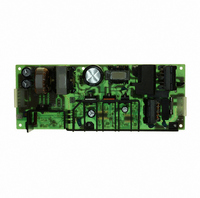
ZWS150PAF24 TDK Corporation, ZWS150PAF24 Datasheet - Page 13

ZWS150PAF24
Manufacturer Part Number
ZWS150PAF24
Description
PWR SUP 24V 151.2W 6.3A
Manufacturer
TDK Corporation
Series
ZWSr
Specifications of ZWS150PAF24
Voltage - Output
24V
Number Of Outputs
1
Power (watts)
150W
Applications
Commercial
Power Supply Type
Switching (Open Frame)
Voltage - Input
85 ~ 265VAC
Mounting Type
Chassis Mount
1st Output
24 VDC @ 6.3A
Size / Dimension
8.19" L x 3.15" W x 1.46" H (208mm x 80mm x 37mm)
Power (watts) - Rated
151.2W
Operating Temperature
-10°C ~ 70°C
Efficiency
82%
Approvals
CE, CSA, EN, UL
Line Regulation
0.4%
Load Regulation
0.8%
Lead Free Status / RoHS Status
Lead free / RoHS Compliant
3rd Output
-
2nd Output
-
4th Output
-
Other names
285-1711
4-2. Mounting Method
PCB type
Please use the mounting hole (4 holes of φ3.5) and insert
the spacer (MAXφ8.0)of height over 8mm to lift the unit.
Also use all 4 mounting holes for the unit installation. The
vibration spec is the value taken when the unit is raised by
8mm spacers.
Note: For cases where the unit is often under vibration
condition, fix with isolated spacer (non conductive), at the
5th hole, near C6 on the PCB.
Example:
Please leave 4mm space from the surfaces and leave
4mm space from the sides of PCB, especially from the
solder surface, 8mm space is necessary. If the space is
not enough, the specification of insulation and withstand
voltage will not be satisfied.
The 5th hole diameter: Φ3.5mm
PCB thickness: 1.6mm
Maximum spacer outer diameter: Φ7mm
R7
Test point
(CORE)
T1
PCB
- 12 -
FG should be connected to the earth terminal of the appa-
ratus. If not, the EMI noise and output noise will increase.
Hatching area is maximum permissible area of metal part
for mounting.(9mm from each PCB corners)
For chassis option /L, chassis & cover option /A
Recommended mounting by following holes A or B, to
meet 19.6m/s
(F) & (G) is prohibited as shown in section 4-1. The power
supply can be mounted through holes A or B.
A: Embossed tapped and countersunk holes by 4-M4
B: Φ4.5 holes and R2.25 slot hole by 3-M4 screws (For
screws
/SL and /SA models, these holes can not be used)
2
vibration specification.Mounting direction
DENSEI-LAMBDA
ZWS150PAF Series
INSTRUCTION MANUAL


