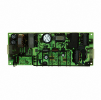
ZWS150PAF24 TDK Corporation, ZWS150PAF24 Datasheet

ZWS150PAF24
Specifications of ZWS150PAF24
Related parts for ZWS150PAF24
ZWS150PAF24 Summary of contents
Page 1
...
Page 2
...
Page 3
ZWS150PAF Input terminal (pin 1 of CN1) Live line (fuse in line input terminal (pin 3 of CN1) Neutral line 3 FG: Input terminal FG (pin 5 of CN1) Safety earth (Frame Ground) ...
Page 4
ZWS150PAF Input terminal L (M4 screw) Live line (fuse in line input terminal N (M4 screw) Neutral line 3 FG: Input terminal FG (M4 screw) Safety earth (Frame Ground) Connect to safety ground ...
Page 5
ZWS150PAF Input terminal L (M4 screw) Live line (fuse in line input terminal N (M4 screw) Neutral line 3 FG: Input terminal FG (M4 screw) Safety earth (Frame Ground) Connect to safety ground ...
Page 6
Terminal Connecting Method Pay attention to the input wiring connected to wrong terminal, the power supply will be damaged. • Input must be off when making connections. • Connect FG terminal of input connector and mount- ...
Page 7
ZWS150PAF/T ZWS150PAF/S DENSEI-LAMBDA ZWS150PAF Series INSTRUCTION MANUAL - 6 - ...
Page 8
Explanation of Functions and Precautions 3-1. Input Voltage Range Input voltage range is single phase 85 ~ 265VAC ( 47 ~ 63Hz ) or 120 ~ 370VDC. Input voltage which is out of specification may cause unit damage. For ...
Page 9
Power Supply Output Terminal Output Terminal (B) To use as Back-up Power Supply 1. Set power supply output voltage higher by the for- ward voltage drop diode F 2. Adjust the output voltage of each power supply to ...
Page 10
Using CN2 It is controlled by short or open between +R & CN2. CN2 is provided in the primary circuit for ON/OFF control by means of a switch or other device. When using this con- nector, which is ...
Page 11
Output ~ FG (Chassis) 500VAC 1min. ( 100mA ) AC(L) AC(N) FG Withstand Voltage Tester 4. Mounting Directions 4-1. Output Derating according to the Mounting Di- rections Recommended standard mounting method Method ( ...
Page 12
Output Derating • Convection cooling PCB type and with chassis type 100 80 Mounting (A),(B) 60 Mounting (C),(D),( - Ambient Temperature (°C) Average Load (%) Convection Mounting 100 ...
Page 13
T1 Test point (CORE) R7 4-2. Mounting Method PCB type Please use the mounting hole (4 holes of φ3.5) and insert the spacer (MAXφ8.0)of height over 8mm to lift the unit. Also use all 4 mounting holes for the unit ...
Page 14
...


