GS-R415 STMicroelectronics, GS-R415 Datasheet - Page 2
GS-R415
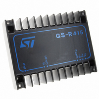
Manufacturer Part Number
GS-R415
Description
IC REG SW STEP DOWN 4A 15V
Manufacturer
STMicroelectronics
Series
GS-R400r
Type
Point of Load (POL) Non-Isolatedr
Datasheet
1.GS-R400V.pdf
(5 pages)
Specifications of GS-R415
Output
15V
Number Of Outputs
1
Power (watts)
60W
Mounting Type
Through Hole
Voltage - Input
19 ~ 46V
Package / Case
Module
1st Output
15 VDC @ 4A
Size / Dimension
3.37" L x 2.64" W x 0.84" H (85.5mm x 67mm x 21.3mm)
Power (watts) - Rated
60W
Operating Temperature
-20°C ~ 85°C
Efficiency
85%
Output Voltage
15 V
Output Current
4 A
Input Voltage
19 V to 46 V
Switching Frequency
100 KHz
Operating Temperature Range
- 20 C to + 85 C
Mounting Style
SMD/SMT
Lead Free Status / RoHS Status
Lead free / RoHS Compliant
3rd Output
-
2nd Output
-
Lead Free Status / Rohs Status
Lead free / RoHS Compliant
Other names
497-8274
GS-R415
GS-R415
Available stocks
Company
Part Number
Manufacturer
Quantity
Price
Company:

Part Number:
GS-R415
Manufacturer:
STMicroelectronics
Quantity:
135


GS-R400 FAMILY
CONNECTION DIAGRAM AND MECHANICAL DATA
PIN DESCRIPTION
2/5
Pin
10
12
11
Dimensions in mm
1
2
3
4
5
6
7
8
9
Inhibit
Reset
+ Input
Input GND
Oscillator
Sync
Current limiting
Output GND
– Sense
+ Sense
+ Output
Program
Function
The module is disabled by a high logic level applied to this pin.
Reset output (GS-R405S only).
DC input voltage. Recommended maximum voltage is 46V.
Return for input voltage source.
100kHz oscillator output. To be connected to Sync (pin 6) input if the unit is a master and
left open if it is a slave (GS-R400VB only). See fig. 5.
Synchronization input. To be connected to the Oscillator output (pin 5) of the master (GS-
R400VB only). See fig. 5.
A resistor ( 2.2k ) connected from this pin to pin 9 sets the current limiting level
(GS-R400VB only).
Return for output current path.
Internally connected to pin 4.
Senses the remote load return. Must be tied to pin 8 when the remote sensing feature is
not used. See fig. 1.
Senses the remote load high side. Must be tied to pin 11 when the remote load sensing
feature is not used. See fig. 1.
Regulated DC output voltage.
A resistor ( 18k ) connected between this pin and pin 10 sets the output voltage
(GS-R400V and GS-R400VB only).
Bottom view
Description
Pin 2
Pin 5,6,7 GS-R400VB only
Pin 12
GS-R405S only
GS-R400V/VB only
Related parts for GS-R415
Image
Part Number
Description
Manufacturer
Datasheet
Request
R

Part Number:
Description:
Bluetooth Class I 3.3V 0.721Mbps 51-Pin T/R
Manufacturer:
STMicroelectronics
Datasheet:

Part Number:
Description:
IC REG SW STEP DOWN 4A 5.1V-40V
Manufacturer:
STMicroelectronics
Datasheet:

Part Number:
Description:
IC REG SW STEP DOWN 4A 5.1V
Manufacturer:
STMicroelectronics
Datasheet:

Part Number:
Description:
IC REG SW STEP DOWN 4A 24V
Manufacturer:
STMicroelectronics
Datasheet:

Part Number:
Description:
CONVERTR MODULE DC-DC 1.8A 12SMD
Manufacturer:
STMicroelectronics
Datasheet:

Part Number:
Description:
CONVERTR MODULE DC-DC 1.9A 12SMD
Manufacturer:
STMicroelectronics
Datasheet:

Part Number:
Description:
CONVERTR MODULE DC-DC 1.8A 15SIP
Manufacturer:
STMicroelectronics
Datasheet:

Part Number:
Description:
CONVERTR MODULE DC-DC 1.9A 15SIP
Manufacturer:
STMicroelectronics
Datasheet:

Part Number:
Description:
CONVERTER MODULE DC-DC 2A 12-SMD
Manufacturer:
STMicroelectronics
Datasheet:

Part Number:
Description:
CONVERTER MODULE DC-DC 2A 12-SMD
Manufacturer:
STMicroelectronics
Datasheet:
Part Number:
Description:
STMicroelectronics [RIPPLE-CARRY BINARY COUNTER/DIVIDERS]
Manufacturer:
STMicroelectronics
Datasheet:
Part Number:
Description:
STMicroelectronics [LIQUID-CRYSTAL DISPLAY DRIVERS]
Manufacturer:
STMicroelectronics
Datasheet:

Part Number:
Description:
BOARD EVAL FOR MEMS SENSORS
Manufacturer:
STMicroelectronics
Datasheet: