LTM4600HVMPV#PBF Linear Technology, LTM4600HVMPV#PBF Datasheet - Page 12
LTM4600HVMPV#PBF
Manufacturer Part Number
LTM4600HVMPV#PBF
Description
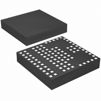
IC DC/DC UMODULE 10A 104-LGA
Manufacturer
Linear Technology
Series
µModuler
Type
Point of Load (POL) Non-Isolatedr
Datasheet
1.LTM4600HVEVPBF.pdf
(24 pages)
Specifications of LTM4600HVMPV#PBF
Output
0.6 ~ 5 V
Number Of Outputs
1
Power (watts)
50W
Mounting Type
Surface Mount
Voltage - Input
4.5 ~ 28 V
Package / Case
104-LGA
1st Output
0.6 ~ 5 VDC @ 10A
Size / Dimension
0.59" L x 0.59" W x 0.11" H (15mm x 15mm x 2.8mm)
Power (watts) - Rated
50W
Operating Temperature
-55°C ~ 125°C
Efficiency
92%
Lead Free Status / RoHS Status
Lead free / RoHS Compliant
3rd Output
-
2nd Output
-
Available stocks
Company
Part Number
Manufacturer
Quantity
Price


APPLICATIO S I FOR ATIO
LTM4600HV
After the controller has been started and given adequate
time to charge up the output capacitor, C
short-circuit timer. After the RUN/SS pin charges above 4V,
if the output voltage falls below 75% of its regulated value,
then a short-circuit fault is assumed. A 1.8μA current then
begins discharging C
the RUN/SS pin drops to 3.5V, then the controller turns
off both power MOSFETs, shuting down the converter
permanently. The RUN/SS pin must be actively pulled
down to ground in order to restart operation.
The over-current protection timer requires the soft-start
timing capacitor C
that the output is in regulation by the time C
the 4V threshold. In general, this will depend upon the size
of the output capacitance, output voltage and load current
characteristic. A minimum external soft-start capacitor
can be estimated from:
Generally 0.1μF is more than suffi cient.
Since the load current is already limited by the current
mode control and current foldback circuitry during a
shortcircuit, over-current latchoff operation is NOT always
needed or desired, especially the output has large amount
of capacitance or the load draw huge current during start
up. The latchoff feature can be overridden by a pull-up
current greater than 5μA but less than 80μA to the RUN/SS
pin. The additional current prevents the discharge of C
during a fault and also shortens the soft-start period. Us-
ing a resistor from RUN/SS pin to V
12
C
SS EXT
_
+
1000
SS
U
pF
SS
be made large enough to guarantee
. If the fault condition persists until
>
C
U
OUT
•
V
OUT
IN
W
is a simple solution
(
10
–
SS
3
SS
[ /
F V
is used as a
has reached
U
S
])
SS
to defeat latchoff. Any pull-up network must be able to
maintain RUN/SS above 4V maximum latchoff threshold
and overcome the 4μA maximum discharge current. Figure
3 shows a conceptual drawing of V
short circuit.
1.5V
R
SWITCHING
V
RUN/SS
STARTS
IN
Figure 3. RUN/SS Pin Voltage During Startup and
Short-Circuit Protection
Figure 4. Defeat Short-Circuit Latchoff with a Pull-Up
Resistor to V
OF I
SOFT-START
3V
CLAMPING
L
RELEASED
V
RUN/SS
PGND SGND
IN
4V
LTM4600HV
IN
SHORT-CIRCUIT
LATCH ARMED
4600hv F04
V
O
V
RUN/SS
RECOMMENDED VALUES FOR RUN/SS
10.8V TO 13.8V
OVERLOAD
4.5V TO 5.5V
HAPPENS
24V TO 28V
OUTPUT
V
IN
RUN
during startup and
SHORT-CIRCUIT
R
RUN/SS
75%V
150k
500k
LATCHOFF
50k
O
4600hvfc
4600hv F03
3.5V
t
t
Related parts for LTM4600HVMPV#PBF
Image
Part Number
Description
Manufacturer
Datasheet
Request
R

Part Number:
Description:
10a, 28vin High Efficiency Dc/dc ?module
Manufacturer:
Linear Technology Corporation
Datasheet:

Part Number:
Description:
IC DC/DC UMODULE 10A 104-LGA
Manufacturer:
Linear Technology
Datasheet:
Part Number:
Description:
IC DC/DC UMODULE 10A 104-LGA
Manufacturer:
Linear Technology
Datasheet:

Part Number:
Description:
10A High Effi ciency DC/DC ?Module
Manufacturer:
LINER [Linear Technology]
Datasheet:

Part Number:
Description:
IC DC/DC UMODULE 10A 104-LGA
Manufacturer:
Linear Technology
Datasheet:
Part Number:
Description:
IC DC/DC UMODULE 10A 104-LGA
Manufacturer:
Linear Technology
Datasheet:

Part Number:
Description:
CD ROM LINEARVIEW DATASHEETS
Manufacturer:
Linear Technology
Part Number:
Description:
Standalone Linear Li-Ion Battery Charger with Thermal Regulation in ThinSOT
Manufacturer:
Linear Technology Corporation
Datasheet:
Part Number:
Description:
Low noise, high frequency, 8th order linear phase lowpass filter
Manufacturer:
Linear Technology Corporation
Datasheet:
Part Number:
Description:
Manufacturer:
Linear Technology Corporation
Datasheet:
Part Number:
Description:
Manufacturer:
Linear Technology Corporation
Datasheet:
Part Number:
Description:
Manufacturer:
Linear Technology Corporation
Datasheet:
Part Number:
Description:
Manufacturer:
Linear Technology Corporation
Datasheet:
Part Number:
Description:
Manufacturer:
Linear Technology Corporation
Datasheet:
Part Number:
Description:
Manufacturer:
Linear Technology Corporation
Datasheet: