LTM4616EV#PBF Linear Technology, LTM4616EV#PBF Datasheet - Page 7
LTM4616EV#PBF
Manufacturer Part Number
LTM4616EV#PBF
Description
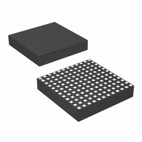
IC DC/DC UMODULE DUAL 8A 144-LGA
Manufacturer
Linear Technology
Series
µModuler
Type
Point of Load (POL) Non-Isolatedr
Datasheet
1.LTM4616EVPBF.pdf
(28 pages)
Specifications of LTM4616EV#PBF
Design Resources
LTM4616 Spice Model
Output
0.6 ~ 5 V
Number Of Outputs
2
Power (watts)
12W
Mounting Type
Surface Mount
Voltage - Input
2.7 ~ 5.5 V
Package / Case
144-LGA
1st Output
0.6 ~ 5 VDC @ 8A
2nd Output
0.6 ~ 5 VDC @ 8A
Size / Dimension
0.59" L x 0.59" W x 0.11" H (15mm x 15mm x 2.8mm)
Power (watts) - Rated
12W
Operating Temperature
-40°C ~ 125°C
Lead Free Status / RoHS Status
Lead free / RoHS Compliant
3rd Output
-
Available stocks
Company
Part Number
Manufacturer
Quantity
Price


pin Functions
MODE1 and MODE2 (A8 and G8): Mode Select Input for
Each Channel. Tying this pin high enables Burst Mode
operation. Tying this pin low enables forced continuous
operation. Floating this pin or tying it to V
pulse-skipping operation.
CLKIN1 and CLKIN2 (A7 and G7): External Synchroniza-
tion Input to Phase Detector for Each Channel. This pin
is internally terminated to SGND with a 50k resistor. The
phase-locked loop will force the internal top power PMOS
turn on to be synchronized with the rising edge of the
CLKIN signal. Connect this pin to SV
spectrum modulation. During external synchronization,
make sure the PLLLPF pin is not tied to V
PLLLPF1 and PLLLPF2 (E6 and L6): Phase-Locked Loop
Lowpass Filter for Each Channel. An internal lowpass filter
is tied to this pin. In spread spectrum mode, placing a
capacitor here to SGND controls the slew rate from one
frequency to the next. Alternatively, floating this pin allows
normal running frequency at 1.5MHz, tying this pin to SV
forces the part to run at 1.33 times its normal frequency
(2MHz), tying it to ground forces the frequency to run at
0.67 times its normal frequency (1MHz).
PHMODE1 and PHMODE2 (A9 and G9): Phase Selector
Input for Each Channel. This pin determines the phase
relationship between the internal oscillator and CLKOUT.
Tie it high for 2-phase operation, tie it low for 3-phase
operation, and float or tie it to V
MGN1 and MGN2 (A10 and G10): Voltage Margining
Pin for Each Channel. Increases or decreases the output
voltage by the amount specified by the BSEL pin. To
disable margining, tie the MGN pin to a voltage divider
with 50k resistors from V
For margining, connect a voltage divider from V
with the center point connected to the MGN pin for the spe-
cific channel. Each resistor should be close to 50k. Margin
High is within 0.3V of V
GND. See the Applications Information section and Figure
18 for margining control. The specified tri-state drivers are
capable of the high and low requirements for margining.
BSEL1 and BSEL2 (A6 and G6): Margining Bit Select Pin
for Each Channel. Tying BSEL low selects ±5% margin
value, tying it high selects 10% margin value. Floating it
or tying it to V
IN
/2 selects 15% margin value.
IN
, and Margin Low is within 0.3V of
IN
to ground (see Figure 5).
IN
/2 for 4-phase operation.
IN
to enable spread
IN
IN
or GND.
/2 enables
IN
to GND
IN
TRACK1 and TRACK2 (E8 and L8): Output Voltage Tracking
Pin for Each Channel. Voltage tracking is enabled when the
TRACK voltage is below 0.57V. If tracking is not desired,
then connect the TRACK pin to SV
to SV
0.18V before the chip shuts down even though RUN is
already low. Do not float this pin. A resistor and capacitor
can be applied to the TRACK pin to increase the soft-start
time of the regulator. TRACK1 and TRACK2 can be tied
together for parallel operation and tracking. See the Ap-
plications Information section.
FB1 and FB2 (D8 and K8): The Negative Input of the Error
Amplifier for Each Channel. Internally, this pin is connected
to V
voltages can be programmed with an additional resistor
between FB and GND pins. In PolyPhase
the FB pins together allows for parallel operation. See the
Applications Information section for details.
I
Error Amplifier Compensation Point for Each Channel. The
current comparator threshold increases with this control
voltage. Tie together in parallel operation.
I
I
SGND for single phase operation on each channel. For
PolyPhase operation, tie the master’s I
connecting all of the I
PGOOD1 and PGOOD2 (A11 and G11): Output Voltage
Power Good Indicator for Each Channel. Open-drain logic
output that is pulled to ground when the output voltage
is not within ±10% of the regulation point. Power good
is disabled during margining.
RUN1 and RUN2 (F6 and M6): Run Control Pin. A voltage
above 1.7V will turn on the module.
SW1 and SW2 (B6 and H6): Switching Node of Each
Channel That is Used for Testing Purposes. This can be
connected to an electronically open circuit copper pad on
the board for improved thermal performance.
CLKOUT1 and CLKOUT2 (F7 and M7): Output Clock
Signal for PolyPhase Operation. The phase of CLKOUT is
determined by the state of the PHMODE pin.
TH1
THM1
TH
Differential Amplifier for Each Channel. Tie this pin to
OUT
and I
IN
and I
, then the TRACK pin’s voltage needs to be below
with a 10k precision resistor. Different output
TH2
THM2
(F8 and M8): Current Control Threshold and
(E7 and L7): Negative Input to the Internal
THM
pins together at the master.
IN
. If TRACK is not tied
THM
LTM4616
®
operation, tying
to SGND while
4616fc
7
Related parts for LTM4616EV#PBF
Image
Part Number
Description
Manufacturer
Datasheet
Request
R

Part Number:
Description:
Dual 8a Per Channel Low Vin Dc/dc ?module
Manufacturer:
Linear Technology Corporation
Datasheet:

Part Number:
Description:
BOARD DEMO LTM4616
Manufacturer:
Linear Technology
Datasheet:

Part Number:
Description:
IC DC/DC UMODULE DUAL 8A 144-LGA
Manufacturer:
Linear Technology
Datasheet:
Part Number:
Description:
CD ROM LINEARVIEW DATASHEETS
Manufacturer:
Linear Technology
Part Number:
Description:
Standalone Linear Li-Ion Battery Charger with Thermal Regulation in ThinSOT
Manufacturer:
Linear Technology Corporation
Datasheet:
Part Number:
Description:
Low noise, high frequency, 8th order linear phase lowpass filter
Manufacturer:
Linear Technology Corporation
Datasheet:
Part Number:
Description:
Manufacturer:
Linear Technology Corporation
Datasheet:
Part Number:
Description:
Manufacturer:
Linear Technology Corporation
Datasheet:
Part Number:
Description:
Manufacturer:
Linear Technology Corporation
Datasheet:
Part Number:
Description:
Manufacturer:
Linear Technology Corporation
Datasheet:
Part Number:
Description:
Manufacturer:
Linear Technology Corporation
Datasheet:
Part Number:
Description:
Manufacturer:
Linear Technology Corporation
Datasheet:
Part Number:
Description:
Manufacturer:
Linear Technology Corporation
Datasheet:
Part Number:
Description:
Dual and Quad, JFET Input Precision High Speed Op Amps
Manufacturer:
Linear Technology Corporation
Datasheet:
Part Number:
Description:
Manufacturer:
Linear Technology Corporation
Datasheet: