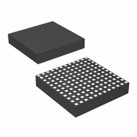
LTM4616EV#PBF Linear Technology, LTM4616EV#PBF Datasheet - Page 13

LTM4616EV#PBF
Manufacturer Part Number
LTM4616EV#PBF
Description
IC DC/DC UMODULE DUAL 8A 144-LGA
Manufacturer
Linear Technology
Series
µModuler
Type
Point of Load (POL) Non-Isolatedr
Datasheet
1.LTM4616EVPBF.pdf
(28 pages)
Specifications of LTM4616EV#PBF
Design Resources
LTM4616 Spice Model
Output
0.6 ~ 5 V
Number Of Outputs
2
Power (watts)
12W
Mounting Type
Surface Mount
Voltage - Input
2.7 ~ 5.5 V
Package / Case
144-LGA
1st Output
0.6 ~ 5 VDC @ 8A
2nd Output
0.6 ~ 5 VDC @ 8A
Size / Dimension
0.59" L x 0.59" W x 0.11" H (15mm x 15mm x 2.8mm)
Power (watts) - Rated
12W
Operating Temperature
-40°C ~ 125°C
Lead Free Status / RoHS Status
Lead free / RoHS Compliant
3rd Output
-
Available stocks
Company
Part Number
Manufacturer
Quantity
Price
applications inForMation
The LTM4616 device is an inherently current mode con-
trolled device, so parallel modules will have very good
current sharing. This will balance the thermals on the
design. Tie the I
share the current. Current sharing is inherently guaranteed
by the current mode operation of the LTM4616’s DC/DC
regulators. Moreover, the accuracy of current sharing be-
tween the two outputs is approximately ±15%. To reduce
ground potential noise, tie the I
together and then connect to the SGND of the master at
the point it connects to the output capacitor GND. See
CLKIN
PHMODE
CLKIN
PHMODE
CLKIN
PHMODE
PHASE 1
PHASE 1
PHASE 4
0
90
CLKOUT
0
CLKOUT
CLKOUT
TH
+120
+120
+120
pins of each LTM4616 together to
CLKIN
PHMODE
CLKIN
PHMODE
CLKIN
PHMODE
V
IN
LTC6908-2
PHASE 3
PHASE 5
PHASE 8
120
120
210
CLKOUT
CLKOUT
CLKOUT
THM
OUT1
OUT2
pins of all LTM4616s
+120
+120
+120
S
S
S
VIN
VIN
VIN
CLKIN
PHMODE
CLKIN
PHMODE
CLKIN
PHMODE
Figure 3. 12-Phase Operation
Figure 2. 6-Phase Operation
PHASE 5
PHASE 12
PHASE 9
240
240
330
CLKOUT
CLKOUT
CLKOUT
+180
+180
+180
layout guideline in Figure 17. Figure 19 shows a schematic
of the parallel design. The FB pins of the parallel module
are tied together.
Input RMS Ripple Current Cancellation
Application Note 77 provides a detailed explanation of
multiphase operation. The input RMS ripple current can-
cellation mathematical derivations are presented, and a
graph is displayed representing the RMS ripple current
reduction as a function of the number of interleaved phases.
Figure 4 shows this graph.
CLKIN
PHMODE
CLKIN
PHMODE
CLKIN
PHMODE
PHASE 2
PHASE 3
PHASE 6
(420)
(420)
(510)
150
60
60
CLKOUT
CLKOUT
CLKOUT
+120
+120
+120
CLKIN
PHMODE
CLKIN
PHMODE
CLKIN
PHMODE
PHASE 10
PHASE 4
PHASE 7
180
180
270
CLKOUT
CLKOUT
CLKOUT
+120
+120
+120
LTM4616
CLKIN
PHMODE
CLKIN
PHMODE
CLKIN
PHMODE
PHASE 6
PHASE 11
PHASE 2
(390)
300
300
30
CLKOUT
CLKOUT
CLKOUT
13
4616 F03
4616fc
4616 F02


