LYYYG6SF-BBDA-35-Z OSRAM Opto Semiconductors Inc, LYYYG6SF-BBDA-35-Z Datasheet - Page 16
LYYYG6SF-BBDA-35-Z
Manufacturer Part Number
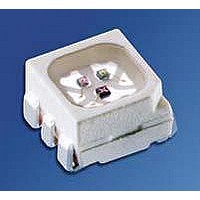
LYYYG6SF-BBDA-35-Z
Description
LED MULTILED PWR YELLOW 6PLCC
Manufacturer
OSRAM Opto Semiconductors Inc
Series
MULTILEDr
Specifications of LYYYG6SF-BBDA-35-Z
Package / Case
6-PLCC
Viewing Angle
120°
Color
Yellow
Millicandela Rating
3920mcd
Current - Test
50mA
Wavelength - Dominant
589nm
Wavelength - Peak
594nm
Voltage - Forward (vf) Typ
2.15V
Lens Type
Diffused
Lens Style/size
Square, 2.5mm
Size / Dimension
3.30mm L x 3.00mm W
Height
2.00mm
Mounting Type
Surface Mount
Resistance Tolerance
589nm
Led Size
3.5 mm x 3 mm
Illumination Color
Yellow
Lens Color/style
Diffused
Operating Voltage
2.15 V
Wavelength
587 nm
Luminous Intensity
2800 mcd to 7100 mcd
Mounting Style
SMD/SMT
Operating Current
70 mA
Lens Shape
50 mA
Maximum Operating Temperature
+ 100 C
Minimum Operating Temperature
- 40 C
Peak Wavelength
594 nm
Wavelength/color Temperature
587 nm
Lead Free Status / RoHS Status
Lead free / RoHS Compliant
Luminous Flux @ Current - Test
-
Lead Free Status / RoHS Status
Lead free / RoHS Compliant, Lead free / RoHS Compliant
Other names
Q65110A4165


Fußnoten:
1)
2)
3)
4)
5)
6)
7)
8)
9)
10)
11)
12)
13)
Published by
OSRAM Opto Semiconductors GmbH
Leibnizstraße 4, D-93055 Regensburg
www.osram-os.com
© All Rights Reserved.
2009-07-10
Helligkeitswerte werden mit einer Stromeinprägedauer
von 25 ms und einer Genauigkeit von ± 11% ermittelt.
Wegen der besonderen Prozessbedingungen bei der
Herstellung von LED können typische oder abgeleitete
technische Parameter nur aufgrund statistischer Werte
wiedergegeben
notwendigerweise mit den Werten jedes einzelnen
Produktes überein, dessen Werte sich von typischen und
abgeleiteten
unterscheiden können. Falls erforderlich, z.B. aufgrund
technischer Verbesserungen, werden diese typischen
Werte ohne weitere Ankündigung geändert.
Die angegebene Helligkeit ist die Summe der Helligkeit
aus 3 Chips bei einem Strom von 50 mA je Chip.
Die LED kann kurzzeitig in Sperrichtung betrieben werden.
R
(Padgröße ≥ 16 mm
Wellenlängen werden mit einer Stromeinprägedauer von
25 ms und einer Genauigkeit von ±1 nm ermittelt.
Spannungswerte werden mit einer Stromeinprägedauer
von 1 ms und einer Genauigkeit von ±0,1 V ermittelt.
Im gestrichelten Bereich der Kennlinien muss mit erhöhten
Helligkeitsunterschieden
innerhalb einer Verpackungseinheit gerechnet werden.
Gehäuse hält TTW-Löthitze aus nach CECC 00802.
Das Gehäuse ist auf Grund der Beinchengeometrie
nicht für TTW-Löten empfohlen, da sich Lötbrücken
bilden können.
Maße werden wie folgt angegeben: mm (inch)
Gehäuse hält TTW-Löthitze aus nach CECC 00802
Ein
lebenserhaltenden Apparaten oder Systemen eingesetzt
wird und dessen Defekt voraussichtlich zu einer
Fehlfunktion dieses lebenserhaltenden Apparates oder
Systems führen wird oder die Sicherheit oder Effektivität
dieses Apparates oder Systems beeinträchtigt.
Lebenserhaltende Apparate oder Systeme sind für
(a) die Implantierung in den menschlichen Körper
oder
(b) für die Lebenserhaltung bestimmt.
Falls sie versagen, kann davon ausgegangen werden,
dass die Gesundheit und das Leben des Patienten in
Gefahr ist.
thJA
kritisches
ergibt sich bei Montage auf PC-Board FR 4
Werten
Bauteil
werden.
2
je Pad)
oder
ist
zwischen
Diese
ein
typischen
Bauteil,
stimmen
Leuchtdioden
Kennlinien
das
nicht
in
16
Remarks:
1)
2)
3)
4)
5)
6)
7)
8)
9)
10)
11)
12)
13)
Brightness groups are tested at a current pulse duration of
25 ms and a tolerance of ± 11%.
Due to the special conditions of the manufacturing
processes of LED, the typical data or calculated
correlations of technical parameters can only reflect
statistical figures. These do not necessarily correspond to
the actual parameters of each single product, which could
differ from the typical data and calculated correlations or
the typical characteristic line. If requested, e.g. because of
technical improvements, these typ. data will be changed
without any further notice.
The stated brightness is a addition of the brightness of
3 chips at a driving current of 50 mA per chip.
Driving the LED in reverse direction is suitable for short
term application.
R
(pad size ≥ 16 mm
Wavelengths are tested at a current pulse duration of
25 ms and a tolerance of ±1 nm.
Forward voltages are tested at a current pulse duration of
1 ms and a tolerance of ±0.1 V.
In the range where the line of the graph is broken, you
must expect higher brightness differences between single
LEDs within one packing unit.
Package able to withstand TTW-soldering heat acc. to
CECC 00802.
The package is not recommended for TTW soldering
because a short cut between the contacts can occure.
Dimensions are specified as follows: mm (inch)
Package able to withstand TTW-soldering heat acc. to
CECC 00802
A critical component is a component used in a life-support
device or system whose failure can reasonably be
expected to cause the failure of that life-support device or
system, or to affect its safety or the effectiveness of that
device or system.
Life support devices or systems are intended
(a) to be implanted in the human body,
or
(b) to support and/or maintain and sustain human life. If
they fail, it is reasonable to assume that the health and the
life of the user may be endangered.
thJA
results from mounting on PC board FR 4
2
per pad)
LYYY G6SF
Related parts for LYYYG6SF-BBDA-35-Z
Image
Part Number
Description
Manufacturer
Datasheet
Request
R

Part Number:
Description:
LED High Power (> 0.5 Watts) Yellow TOPLED
Manufacturer:
OSRAM Opto Semiconductors Inc

Part Number:
Description:
LED MLT PWR TLED 587NM YEL 6PLCC
Manufacturer:
OSRAM Opto Semiconductors Inc
Datasheet:

Part Number:
Description:
INTELLIGENT DISP 4CHAR 5X7 HERED
Manufacturer:
OSRAM Opto Semiconductors Inc
Datasheet:

Part Number:
Description:
DISPLAY 8DIGIT CERAMIC GREEN
Manufacturer:
OSRAM Opto Semiconductors Inc
Datasheet:

Part Number:
Description:
EMITTER IR 950NM 5MM SMD RADIAL
Manufacturer:
OSRAM Opto Semiconductors Inc
Datasheet:

Part Number:
Description:
LED TOPLED GREEN 570NM 2-PLCC
Manufacturer:
OSRAM Opto Semiconductors Inc
Datasheet:

Part Number:
Description:
INTERRUPTER RELFECT W/FILTR SMD
Manufacturer:
OSRAM Opto Semiconductors Inc
Datasheet:

Part Number:
Description:
LED Displays 5x7 Green 0.145 , 4-CHARACTER
Manufacturer:
OSRAM Opto Semiconductors Inc
Datasheet:
Part Number:
Description:
Q65110A4321_SIDELED PURE GREEN EOL150407
Manufacturer:
OSRAM Opto Semiconductors Inc
Datasheet:
Part Number:
Description:
Q65110A1202_RO DETECTOR 3/5MM_TR_RO
Manufacturer:
OSRAM Opto Semiconductors Inc
Datasheet:

Part Number:
Description:
PHOTODIODE 900NM 3MM W/FILTER
Manufacturer:
OSRAM Opto Semiconductors Inc
Datasheet:

Part Number:
Description:
PHOTODIODE 860NM 3MM CLEAR
Manufacturer:
OSRAM Opto Semiconductors Inc
Datasheet:

Part Number:
Description:
PHOTODIODE 900NM 5MM W/FILTER
Manufacturer:
OSRAM Opto Semiconductors Inc
Datasheet:

Part Number:
Description:
PHOTODIODE 880NM W/FLTR THRUHOLE
Manufacturer:
OSRAM Opto Semiconductors Inc
Datasheet: