AFCT-5964NLZ Avago Technologies US Inc., AFCT-5964NLZ Datasheet
AFCT-5964NLZ
Specifications of AFCT-5964NLZ


Related parts for AFCT-5964NLZ


AFCT-5964NLZ Summary of contents
Page 1
... Temperature range: AFCT-5964TLZ: 0°C to +70 °C, AFCT-5964ATLZ: -40 °C to +85 °C, AFCT-5964NLZ: -5 °C to +70 °C, • Wave solder and aqueous wash process compatible • Manufactured in an ISO9002 certified facility • Fully Class 1 CDRH/IEC 825 compliant • +3.3 V TTL signal detect output • ...
Page 2
... Functional Description Receiver Section Design The receiver section for the AFCT-5964TLZ/ TGZ/ATLZ/ATGZ/NLZ/NGZ contains an InGaAs/ InP photo detector and a preamplifier mounted in an optical subassembly. This optical subassembly is coupled to a postamp/decision circuit on a circuit board. The design of the optical assembly is such that it provides better than 14 dB Optical Return Loss (ORL) ...
Page 3
... Functional Description Transmitter Section Design A schematic diagram for the transmitter is shown in Figure 2. The AFCT-5964TLZ/TGZ/ ATLZ/ATGZ/NLZ/NGZ incorporates an FP laser as its optical source. All part numbers have been designed to be compliant with IEC 825 eye safety requirements under any single fault condition and CDRH under normal operating conditions ...
Page 4
Package The overall package concept for these devices consists of the following basic elements; two optical subassemblies, a electrical subassembly and the housing as illustrated in the block diagram in Figure 3. The package outline drawing and pin out are ...
Page 5
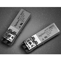
... FRONT VIEW G MODULE - NO EMI SHIELD DIMENSIONS IN MILLIMETERS (INCHES) DIMENSIONS SHOWN ARE NOMINAL. ALL DIMENSIONS MEET THE MAXIMUM PACKAGE OUTLINE DRAWING IN THE SFF MSA. Figure 4. AFCT-5964TLZ/TGZ/ATLZ/ATGZ/NLZ/NGZ Package Outline Drawing 5 TOP VIEW SIDE VIEW SIDE VIEW BOTTOM VIEW BACK VIEW ...
Page 6
Pin Descriptions: Pin 1 Photo Detector Bias, VpdR: This pin enables monitoring of photo detector bias current. It must be connected directly through a resistor (Max 200 Ω) for monitoring photo ...
Page 7
... Figures 6a and 6b show recommended dc and ac coupled circuits for deploying the Avago Technologies transceivers in +3.3 V systems. Data Line Interconnections Avago Technologies’ AFCT-5964TLZ/TGZ/ATLZ/ ATGZ/NLZ/NGZ fiber-optic transceivers are designed to couple to +3.3 V PECL signals. The transmitter driver circuit regulates the output optical power. The regulated light output will ...
Page 8
... Note C: THE BIAS RESISTOR FOR VpdR SHOULD NOT EXCEED 200 Ω AND C5 ARE OPTIONAL BYPASS CAPACITORS FOR ADDITIONAL LOW FREQUENCY NOISE FILTERING. Figure 6b. Recommended ac coupled interface circuit The AFCT-5964TLZ/TGZ/ATLZ/ATGZ/NLZ/NGZ have a transmit disable function which is a single-ended +3.3 V TTL input which is dc- coupled to pin 13 ...
Page 9
... EMI suppression. Avago Technologies encourages using standard RF suppression practices and avoiding poorly EMI-sealed enclosures. Avago Technologies OC-3 LC transceivers (AFCT- 5964TLZ/TGZ/ATLZ/ATGZ/NLZ/NGZ) have nose shields which provide a convenient chassis connection to the nose of the transceiver. This nose shield improves system EMI performance by effectively closing off the LC aperture ...
Page 10
... Recommended Solder and Wash Process The AFCT-5964TLZ/TGZ/ATLZ/ATGZ/NLZ/NGZ are compatible with industry-standard wave solder processes. Process plug This transceiver is supplied with a process plug for protection of the optical port within the LC connector receptacle. This process plug prevents contamination during wave solder and aqueous rinse as well as during handling, shipping and storage ...
Page 11
Regulatory Compliance The Regulatory Compliance for transceiver performance is shown in Table 1. The overall equipment design will determine the certification level. The transceiver performance is offered as a figure of merit to assist the designer in considering their use ...
Page 12
... CAUTION: There are no user serviceable parts nor any maintenance required for the AFCT-5964TLZ/ TGZ/ATLZ/ATGZ/NLZ/NGZ. All adjustments are made at the factory before shipment to our customers. Tampering with or modifying the performance of the parts will result in voided product warranty. It may also result in improper operation of the circuitry, and possible overstress of the laser source ...
Page 13
Absolute Maximum Ratings Stresses in excess of the absolute maximum ratings can cause catastrophic damage to the device. Limits apply to each parameter in isolation, all other parameters having values within the recommended operating conditions. It should not be assumed ...
Page 14
... Data Input Current - Low Transmitter Differential Data Input Current - High Laser Diode Bias Monitor Voltage Power Monitor Voltage Receiver Electrical Characteristics AFCT-5964TLZ/TGZ 0°C to +70 ° AFCT-5964NLZ/NGZ °C to +70 ° AFCT-5964ATLZ/ATGZ -40 °C to +85 ° Parameter Supply Current Power Dissipation Data Output Voltage Swing (single-ended) ...
Page 15
... Center Wavelength Spectral Width - rms Optical Rise Time Optical Fall Time Extinction Ratio Output Optical Eye Receiver Optical Characteristics AFCT-5964TLZ/TGZ 0°C to +70 ° AFCT-5964NLZ/NGZ °C to +70 ° AFCT-5964ATLZ/ATGZ -40 °C to +85 ° Parameter Receiver Sensitivity Receiver Overload Input Operating Wavelength Signal Detect - Asserted ...
Page 16
... FP Laser (Temperature range 0°C to +70 °C) AFCT-5964TLZ = connector, AFCT-5964TGZ = connector, 1300 nm FP Laser (Temperature range -5 °C to +70 °C) AFCT-5964NLZ = connector. AFCT-5964NGZ = connector. 1300 nm FP Laser (Temperature range -40 °C to +85 °C) AFCT-5964ATLZ = connector. IR, +3.3 V TTL SD with EMI nose shield AFCT-5964ATGZ = connector, IR, +3.3 V TTL SD without EMI nose shield ...