AFBR-53B3EZ Avago Technologies US Inc., AFBR-53B3EZ Datasheet - Page 4
AFBR-53B3EZ
Manufacturer Part Number
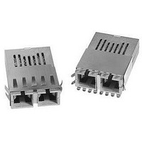
AFBR-53B3EZ
Description
TXRX OPTICAL 5V GBE/FC 1X9
Manufacturer
Avago Technologies US Inc.
Datasheet
1.AFBR-53B3EZ.pdf
(12 pages)
Specifications of AFBR-53B3EZ
Applications
Ethernet
Data Rate
1Gbps
Wavelength
850nm
Voltage - Supply
4.75 V ~ 5.25 V
Connector Type
SC
Mounting Type
Through Hole
Supply Voltage
5V
Wavelength Typ
850nm
Leaded Process Compatible
Yes
Lead Free Status / RoHS Status
Lead free / RoHS Compliant


APPLICATION SUPPORT
Optical Power Budget and Link Penalties
The worst-case Optical Power Budget (OPB) in
dB for a fiber-optic link is determined by the
difference between the minimum transmitter
output optical power (dBm avg) and the lowest
receiver sensitivity (dBm avg). This OPB provides
the necessary optical signal range to establish
a working fiber-optic link. The OPB is allocated
for the fiber-optic cable length and the
corresponding link penalties. For proper link
performance, all penalties that affect the link
performance must be accounted for within the
link optical power budget.
Data Line Interconnections
Avago Technologies’ AFBR-53B3EZ fiber-optic
transceiver is designed for PECL compatible
signals on the Tx data lines. The transmitter
inputs are internally ac-coupled to the laser
driver circuit from the transmitter input pins
(pins 7, 8). The transmitter driver circuit for
the laser light source is an ac-coupled circuit.
This circuit regulates the output optical power.
The regulated light output will maintain a
constant output optical power provided the
data pattern is reasonably balanced in duty
factor. If the data duty factor has long,
continuous state times (low or high data duty
factor), then the output optical power will
gradually change its average output optical power
level to its preset value.
The receiver section is internally ac-coupled
between the preamplifier and the post-amplifier
stages. The actual Data and Data- bar outputs
of the post-amplifier are dc-coupled to their
respective output pins (pins 2, 3). Signal Detect
is a single-ended, PECL output signal that is
dc-coupled to pin 4 of the module. Signal
Detect should not be ac-coupled externally to
the follow-on circuits because of its infrequent
state changes.
Caution should be taken to account for the
proper interconnection between the supporting
Physical Layer integrated circuits
AFBR-53B3EZ transceiver. Figure 3 illustrates
a
interconnecting to a PECL compatible fiber-
optic transceiver.
4
r e c o m m e n d e d
i n t e r f a c e
c i r c u i t f o r
and this
Eye Safety Circuit
For an optical transmitter device to be eye-
safe in the event of a single fault failure, the
transmitter must either maintain normal, eye-
safe operation or be disabled.
In the AFBR-53B3EZ there are three key
elements to the laser driver safety circuitry: a
monitor diode, a window detector circuit, and
direct control of the laser bias. The window
detection circuit monitors the average optical
power using the monitor diode. If a fault
occurs such that the transmitter dc regulation
circuit cannot maintain the preset bias conditions
for the laser emitter within ± 20%, the
transmitter will automatically be disabled. Once
this has occurred, only an electrical power
reset will allow an attempted turn-on of the
transmitter.
Signal Detect
The Signal Detect circuit provides a PECL low
output signal when the optical link is broken
or when the transmitter is off. The Signal
Detect threshold is set to transition from a
high to low state between the minimum receiver
input optional power and –30 dBm avg. input
optical power indicating a definite optical fault
(e.g. unplugged connector for the receiver or
transmitter, broken fiber, or failed far-end
transmitter or data source). A Signal Detect
indicating a working link is functional when
receiving encoded 8B/10B characters. The Signal
Detect does not detect receiver data error or
error-rate. Data errors are determined by signal
processing following the transceiver.
Electromagnetic Interference (EMI)
One of a circuit board designer’s foremost
concerns is the control of electromagnetic
emissions from electronic equipment. Success
in controlling generated Electromagnetic
Interference (EMI) enables the designer to pass
a governmental agency’s EMI regulatory standard;
and more importantly, it reduces the possibility
of interference to neighboring equipment. The
EMI performance of an enclosure using these
transceivers is dependent on the chassis design.
Avago Technologies encourages using standard
RF suppression practices and avoiding poorly
EMI-sealed enclosures.
Related parts for AFBR-53B3EZ
Image
Part Number
Description
Manufacturer
Datasheet
Request
R

Part Number:
Description:
650nm FE Transceiver Eval Kit
Manufacturer:
Avago Technologies US Inc.
Datasheet:

Part Number:
Description:
TXRX OPT OC3 MTRJ SFF 2X5DIP
Manufacturer:
Avago Technologies US Inc.
Datasheet:

Part Number:
Description:
TXRX ETHERNET 125MBD MMF 2X5
Manufacturer:
Avago Technologies US Inc.
Datasheet:

Part Number:
Description:
TXRX OPT SFP DGTL 850NM IND
Manufacturer:
Avago Technologies US Inc.
Datasheet:

Part Number:
Description:
TXRX OPT SFF 4/2/1GBD 2X7
Manufacturer:
Avago Technologies US Inc.
Datasheet:

Part Number:
Description:
TXRX OPT SFP 4/2/1GBD 850NM
Manufacturer:
Avago Technologies US Inc.
Datasheet:

Part Number:
Description:
TXRX OPT XFP 10GB/S 850NM
Manufacturer:
Avago Technologies US Inc.
Datasheet:

Part Number:
Description:
TXRX OPT 1X9 100MBPS ST EXT TEMP
Manufacturer:
Avago Technologies US Inc.
Datasheet:

Part Number:
Description:
TXRX OPT 1X9 100MBPS SC EXT TEMP
Manufacturer:
Avago Technologies US Inc.
Datasheet:

Part Number:
Description:
TXRX OPT 1X9 100MBPS DUPLEX SC
Manufacturer:
Avago Technologies US Inc.
Datasheet:

Part Number:
Description:
OPTOCOUPLER GATE DRV 2A 16-SOIC
Manufacturer:
Avago Technologies US Inc.
Datasheet:
Part Number:
Description:
OPTOCOUPLER 2CH 2.5A 16-SOIC
Manufacturer:
Avago Technologies US Inc.
Datasheet:

Part Number:
Description:
OPTOCOUPLER GATE DRV 0.4A 16SOIC
Manufacturer:
Avago Technologies US Inc.
Datasheet:

Part Number:
Description:
OPTOCOUPLER 2.0A 250KHZ 8-DIP
Manufacturer:
Avago Technologies US Inc.
Datasheet:

Part Number:
Description:
OPTOCOUPLER 2.0A 250KHZ GW 8-SMD
Manufacturer:
Avago Technologies US Inc.
Datasheet: