AFBR-53B3EZ Avago Technologies US Inc., AFBR-53B3EZ Datasheet
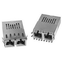
AFBR-53B3EZ
Specifications of AFBR-53B3EZ


Related parts for AFBR-53B3EZ


AFBR-53B3EZ Summary of contents
Page 1
... The high speed output lines are internally ac-coupled and differentially terminated with a 100 W resistor. Receiver Section The receiver of the AFBR-53B3EZ includes a GaAs PIN photodiode mounted together with a custom, silicon bipolar transimpedance preamplifier OSA. This OSA is mated to a custom silicon bipolar circuit that provides post- amplification and quantization ...
Page 2
... Package and Handling Instructions Flammability The AFBR-53B3EZ transceiver housing is made of high strength, heat resistant, chemically resistant and UL 94V-0 flame retardant plastic. Recommended Solder and Wash Process The AFBR-53B3EZ is compatible with industry- standard wave or hand solder processes. Process Plug This transceiver is supplied with a process plug (HFBR-5000) for protection of the optical ports within the duplex SC connector receptacle ...
Page 3
... Equipment nonapproved optical source, operating above the recommended absolute maximum conditions or operating the AFBR-53B3EZ in a manner inconsistent with its design and function may result in hazardous radiation exposure and may be considered an act of modifying or manufacturing a laser product. The person(s) performing such an act is required by law to recertify and reidentify the laser product under the provisions of U ...
Page 4
... In the AFBR-53B3EZ there are three key elements to the laser driver safety circuitry: a monitor diode, a window detector circuit, and direct control of the laser bias. The window detection circuit monitors the average optical power using the monitor diode ...
Page 5
Absolute Maximum Ratings Stresses in excess of the absolute maximum ratings can cause catastrophic damage to the device. Limits apply to each parameter in isolation, all other parameters having values within the recommended operating conditions. It should not be assumed ...
Page 6
... AFBR-53B3EZ, 850 nm VCSEL Transmitter Electrical Characteristics (T = 0°C to +70° Parameter Supply Current Power Dissipation Data Input Current - Low Data Input Current - High Laser Reset Voltage Receiver Electrical Characteristics (T = 0°C to +70° Parameter Supply Current Power Dissipation Data Output Voltage - Low ...
Page 7
... AFBR-53B3EZ, 850 nm VCSEL Transmitter Optical Characteristics (T = 0°C to +70° Parameter Output Optical Power 50/125 µ 0.20 Fiber Output Optical Power 62.5/125 µ 0.275 Fiber Optical Extinction Ratio Center Wavelength Spectral Width - rms Optical Rise/Fall Time RIN 12 Coupled Power Ratio ...
Page 8
... They should be soldered into plated-through holes on the printed circuit board Receiver Signal Ground EER Directly connect this pin to receiver signal ground plane. (For AFBR-53B3 RD+ Receiver Data Out RD open emitter output circuit. Termination is done externally to the module. 3 RD– ...
Page 9
... URFACE-MOUNT COMP ONENTS FOR OP TIMUM HIGH-FREQUENCY P ERFORMANCE MICROS TRIP OR S TRIP LINE FOR S IGNAL P ATHS . LOCATE 50 TERMINATIONS AT THE INP UTS OF RECEIVING UNITS . Figure 3. Recommended Gigabit/sec Ethernet AFBR-53B3EZ Fiber-Optic Transceiver and HDMP-1636A/1646A SERDES Integrated Circuit Transceiver Interface and Power Supply Filter Circuits. 20.32 (0.800) 20.32 (0 ...
Page 10
... DIMENS IONS ARE IN MILLIMETERS (INCHES ). ALL DIMENS IONS ARE ±0.025 m m UNLES S OTHERWIS ECIFIED. Figure 5. Package outline for AFBR-53B3EZ. 10 39.6 12.7 MAX. (0.50) AREA RES ERVED FOR P ROCES S P LUG 25.8 MAX ...
Page 11
... P CB BOTTOM VIEW Figure 6. Suggested module positioning and panel cut-out for AFBR-53B3EZ. 11 25.76 (1.014) 2X 0.8 (0.032) 2X 0.8 (0.032) 27.4 ± 0.50 (1.08 ± 0.02) 6.35 (0.25) MODULE P ROTRUS ION +0.5 -0. +0.02 -0.01 ...
Page 12
... Ordering Information 850 nm VCSEL (SX – Short Wavelength Laser) AFBR-53B3EZ Extended shield, plastic housing. For product information and a complete list of distributors, please go to our web site: Avago, Avago Technologies, and the A logo are trademarks of Avago Technologies, Limited in the United States and other countries. ...