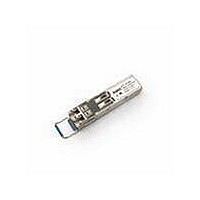
AFCT-5710PZ Avago Technologies US Inc., AFCT-5710PZ Datasheet - Page 8

AFCT-5710PZ
Manufacturer Part Number
AFCT-5710PZ
Description
TXRX OPT SFF PLUGGABLE BAIL
Manufacturer
Avago Technologies US Inc.
Series
-r
Datasheet
1.AFCT-5710LZ.pdf
(19 pages)
Specifications of AFCT-5710PZ
Data Rate
1.25Gbd
Wavelength
1310nm
Applications
Ethernet
Voltage - Supply
3.14 V ~ 3.47 V
Connector Type
LC Duplex
Mounting Type
SFP
Function
SFP Optical Transceivers with Optional DMI for Gigabit Ethernet 1.25 GBd. Intended for premise, public and access networking applications.
Product
Transceiver
Maximum Rise Time
0.26 ns/0.4 ns
Maximum Fall Time
0.26 ns/0.4 ns
Pulse Width Distortion
0.227 ns (Max)/0.267 ns (Max)
Operating Supply Voltage
3.14 V to 3.47 V
Maximum Operating Temperature
+ 85 C
Minimum Operating Temperature
- 10 C
Package / Case
SFP
Optical Fiber Type
TX/RX
Data Transfer Rate
1250MBd
Optical Rise Time
0.26/0.4ns
Optical Fall Time
0.26/0.4ns
Jitter
0.227/0.267ns
Operating Temperature Classification
Commercial
Peak Wavelength
1355nm
Package Type
SFP
Operating Supply Voltage (min)
3.14V
Operating Supply Voltage (typ)
3.3V
Operating Supply Voltage (max)
3.47V
Operating Temp Range
-10C to 85C
Mounting
Snap Fit To Panel
Pin Count
20
Lead Free Status / RoHS Status
Lead free / RoHS Compliant
For Use With
Singlemode Glass
Lead Free Status / RoHS Status
Lead free / RoHS Compliant, Lead free / RoHS Compliant
Available stocks
Company
Part Number
Manufacturer
Quantity
Price
Company:
Part Number:
AFCT-5710PZ
Manufacturer:
Avago Technologies
Quantity:
135
Table 3. Absolute Maximum Ratings
Absolute maximum ratings are those values beyond which functional performance is not intended, device reliabil-
ity is not implied, and damage to the device may occur.
Table 4. Recommended Operating Conditions
Typical operating conditions are those values for which functional performance and device reliability is implied.
Table 5. Transceiver Electrical Characteristics
Notes:
1
2. Over temperature and Beginning of Life.
3. MSA filter is required on host board 10 Hz to 1 MHz. See Figure 3
4. LVTTL, External 4.7 - 10 K: Pull-Up Resistor required
5. LVTTL, Internal 4.7 - 10 K: Pull-Up Resistor required for TX_Disable
6. Internally ac coupled and terminated (100 Ohm differential)
7. Internally ac coupled and load termination located at the user SerDes
8. Per IEEE 802.3
8
Parameter
Storage Temperature (non-operating)
Relative Humidity
Case Temperature
Supply Voltage
Control Input Voltage
Parameter
Case Operating Temperature
Supply Voltage
Parameter
Module supply current
Power Dissipation
AC Electrical Characteristics
Power Supply Noise Rejection (peak - peak)
Inrush Current
DC Electrical Characteristics
Sense Outputs:
Transmit Fault (TX_FAULT)
Loss of Signal (LOS) MOD-DEF2
Control Inputs:
Transmitter Disable (TX_DISABLE)
MOD-DEF1, 2
Data Input:
Transmitter Differential Input Voltage (TD+/-)
Data Ouput:
Receiver Differential Output Voltage (RD+/-)
Receiver Data Rise and Fall Times
Receiver Contributed Total Jitter
AFCT-5710LZ/PZ & AFCT-5715LZ/PZ
AFCT-5710ALZ/APZ & AFCT-5715ALZ/APZ
The module supply voltages, V
cc
T and V
cc
R, must not differ by more than 0.5V or damage to the device may occur.
Symbol
I
P
PSNR
V
V
V
V
V
V
T
TJ
CC
rf
DISS
OH
OL
IH
IL
I
O
Symbol
T
RH
T
V
V
Symbol
T
T
V
S
C
CC
I
C
C
CC
Minimum
2.0
2.0
500
370
Minimum
-10
-40
3.14
Minimum
-40
5
-40
-0.5
-0.5
Typical
200
660
100
Typical
3.3
Maximum
+100
95
85
3.8
V
CC
+0.5
Maximum
240
830
30
VccT, R+0.3
0.8
Vcc
0.8
2400
1600
400
0.33267
Maximum
+85
+85
3.47
Unit
° C
%
° C
V
V
Unit
mA
mW
mV
mA
V
V
V
V
mV
mV
ps
UIps
Unit
° C
° C
V
Notes
1
Notes
Notes
2
2
3
4
4,5
6
7
8


