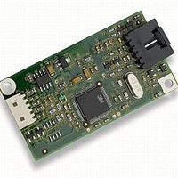
EXII-7719UC 3M, EXII-7719UC Datasheet - Page 20

EXII-7719UC
Manufacturer Part Number
EXII-7719UC
Description
CONTROLLER EXII USB 1X2 CAPAC
Manufacturer
3M
Series
MicroTouch™ Controller EXr
Specifications of EXII-7719UC
Accessory Type
Touch Screen - Controller
Operating Supply Voltage
5 VDC
Resolution
16 K x 16 K
For Use With/related Products
ClearTek™ Touch Screens
Lead Free Status / RoHS Status
Lead free / RoHS Compliant
Other names
3M5766
98-0003-1996-6
98-0003-1996-6
20
Controller Status Request 6
Y = 767 - (768 x 1/8) = 767 - 96 = 671
X = 0 + (1024 x 1/8) = 0 + 128 = 128
Lower Left Calibration Target
*The coordinates are in video terms, with the origin (0, 0) in the upper left corner of the sensor. Examples from the
controller’s perspective, however, place the origin at the lower left corner of the sensor (numbers in brackets). The
controller outputs 0 to 64K on both axes independent of display screen resolution.
Response
The device stalls endpoint 0 if the request cannot be processed successfully. The host
should issue status requests to determine the status of this request. A command status of 1
indicates that the controller is waiting for a touch in the lower left quadrant. A status of 2
indicates that the lower left touch has been completed and the controller is waiting for a
touch in the upper right quadrant. A status of 3 indicates that the upper right touch has
been completed. A status of 0 indicates that the request has failed. A soft reset command
should be sent if the host wishes to terminate calibration.
Determining Target Areas
The default calibration targets (points) are located 12.5% (1/8) inward from the corners of
the video image. For example, suppose the resolution of your Windows-based display is
1024 x 768. The Calibrate Extended command calculates the amount to move inward as
follows:
The Calibrate Extended command then positions the first calibration target inward from
the lower left corner (0,767) and the second calibration target inward from the upper right
corner (1023,0). The following illustration shows how the calibration targets are
calculated for a Windows-based system. Your operating system may be different.
This is a request to send information that indicates the status of the controller. Use this
request to determine whether there were any power on check errors and whether the last
request was completed successfully.
The Controller Status Request is used to poll the controller for command completion
when a previous USB request involved a controller reset. Refer to the Reset Request 7 for
additional details.
• Amount to move inward in the X direction: 1024 x 1/8 = 128
• Amount to move inward in the Y direction: 768 x 1/8 = 96
(0, 767) [0, 1024]*
(0, 0) [0, 0]*
3M Touch Systems, Inc. Proprietary Information
(128, 671)
3M™ MicroTouch™ Controller EX USB Reference Guide
(895, 96)
(
1023, 0) [1024, 0]*
Upper Right Calibration Target
X = 1023 – (1024 x 1/8) = 1023 – 128 = 895
Y = 0 + (768 x 1/8) = 0 + 96 = 96
[1024, 1024]*


