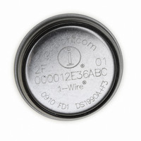
DS1921Z-F5# Maxim Integrated Products, DS1921Z-F5# Datasheet - Page 13

DS1921Z-F5#
Manufacturer Part Number
DS1921Z-F5#
Description
IBUTTON THERMOCHRON F5
Manufacturer
Maxim Integrated Products
Series
iButton®r
Specifications of DS1921Z-F5#
Rohs Information
IButton RoHS Compliance Plan
Memory Size
512B
Memory Type
NVSRAM (Non-Volatile SRAM)
Lead Free Status / RoHS Status
Lead free / RoHS Compliant
The DS1921G measures temperatures with a resolution
of 0.5°C. Temperature values are represented in a sin-
gle byte as an unsigned binary number, which trans-
lates into a theoretical range of 128°C. The range,
however, has been limited to values from 0000 0000
(00h) through 1111 1010 (FAh). The codes 01h to F9h
are considered valid temperature readings.
If a temperature conversion yields a temperature that is
out of range, it is recorded as 00h (if too low) or FAh (if
too high). Since out-of-range results are accumulated in
histogram bins 0 and 62 (see the Temperature Logging
and Histogram section), the data in these bins is of lim-
ited value. For this reason the specified temperature
range of the DS1921G is considered to begin at code
04h and end at code F7h, which corresponds to his-
togram bins 1 to 61.
With T[7…0] representing the decimal equivalent of a tem-
perature reading, the temperature value is calculated as
This equation is valid for converting temperature read-
ings stored in the data-log memory as well as for data
read from the Forced Temperature Conversion Readout
register (address 0211h).
ADDRRESS
ADDRESS
020Dh
020Bh
020Ch
ϑ(°C) = T[7…0]/2 - 40.0
BIT 7
BIT 7
______________________________________________________________________________________
Temperature Conversion
BIT 6
BIT 6
BIT 5
BIT 5
Temperature High Alarm Threshold
Temperature Low Alarm Threshold
BIT 4
BIT 4
Sample Rate
To specify the temperature alarm thresholds, this equa-
tion needs to be resolved to
A value of 23°C, for example, thus translates into 126
decimal or 7Eh. This corresponds to the binary patterns
0111 1110, which could be written to a Temperature
Alarm register (address 020Bh and 020Ch, respectively).
The content of the Sample Rate register (address
020Dh) determines how many minutes the temperature
conversions are apart from each other during a mission.
The sample rate can be any value from 1 to 255, coded
as an unsigned 8-bit binary number. If the memory has
been cleared (Status register bit MEMCLR = 1) and a
mission is enabled (Control register bit EM = 0), writing
a nonzero value to the Sample Rate register starts a mis-
sion. For a full description of the correct sequence of
steps to start a temperature-logging mission, see the
Missioning or Mission Example: Prepare and Start a
New Mission sections.
Thermochron iButton
BIT 3
BIT 3
Temperature Alarm Register Map
T[7…0] = 2 x ϑ(°C) + 80.0
Sample Rate Register Map
BIT 2
BIT 2
BIT 1
BIT 1
Sample Rate
BIT 0
BIT 0
13


