DS1921Z-F5# Maxim Integrated Products, DS1921Z-F5# Datasheet - Page 11

DS1921Z-F5#
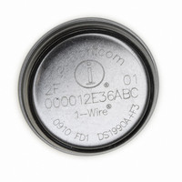
Manufacturer Part Number
DS1921Z-F5#
Description
IBUTTON THERMOCHRON F5
Manufacturer
Maxim Integrated Products
Series
iButton®r
Specifications of DS1921Z-F5#
Rohs Information
IButton RoHS Compliance Plan
Memory Size
512B
Memory Type
NVSRAM (Non-Volatile SRAM)
Lead Free Status / RoHS Status
Lead free / RoHS Compliant
Figure 6. Register Pages Map (continued)
The RTC/alarm and calendar information is accessed
by reading/writing the appropriate bytes in the register
page, address 0200h to 0206h. Note that some bits are
set to 0. These bits always read 0 regardless of how
they are written. The contents of the time, calendar, and
alarm registers are in the binary-coded decimal (BCD)
format.
The RTC of the DS1921G can run in either 12hr or 24hr
mode. Bit 6 of the Hours register (address 0202h) is
defined as the 12hr or 24hr mode select bit. When high,
the 12hr mode is selected. In the 12hr mode, bit 5 is the
AM/PM bit with logic 1 being PM. In the 24hr mode, bit
5 is the 20hr bit (20hr to 23hr).
* The left entry in the ACCESS column is valid between missions. The right entry shows the applicable access mode while a
mission is in progress.
** While a mission is in progress, these addresses can be read. The first attempt to write to these registers (even read-only
ones), however, ends the mission and overwrites selected writable registers.
ADDRESS
021Ah
021Bh
021Ch
021Dh
021Eh
0210h
0211h
0212h
0213h
0214h
0215h
0216h
0217h
0218h
0219h
021Fh
Detailed Register Descriptions
BIT 7
TCB
______________________________________________________________________________________
MEMCLR
BIT 6
Temperature Read-Out (Forced Conversion)
BIT 5
MIP
RTC/Calendar
(No function, reads 00h)
Timekeeping
BIT 4
SIP
Center Byte
Center Byte
High Byte
High Byte
High Byte
Low Byte
Low Byte
Low Byte
Minutes
Month
Hours
Date
Year
BIT 3
0
To distinguish between the days of the week, the
DS1921G includes a counter with a range from 1 to 7.
The assignment of a counter value to the day of week is
arbitrary. Typically, the number 1 is assigned to a
Sunday (U.S. standard) or to a Monday (European stan-
dard).
The calendar logic is designed to automatically com-
pensate for leap years. For every year value that is
either 00 or a multiple of four, the device adds a 29th of
February. This works correctly up to (but not including)
the year 2100.
The DS1921G is Y2K compliant. Bit 7 (CENT) of the
Months register at address 0205h serves as a century
flag. When the Year register rolls over from 99 to 00, the
century flag toggles. It is recommended to write the
century bit to a 1 when setting the RTC to a time/date
between the years 2000 and 2099.
BIT 2
TLF
Thermochron iButton
BIT 1
THF
BIT 0
TAF
Mission Start
Temperature
Timestamp
FUNCTION
Samples
Samples
Mission
Mission
Counter
Counter
Device
Status
Delay
—
R/W
R/W
ACCESS*
R
R
R
R
R
R/W**
R/W
R**
R**
R
R
R
11


