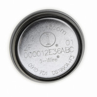
DS1922E-F5# Maxim Integrated Products, DS1922E-F5# Datasheet - Page 20

DS1922E-F5#
Manufacturer Part Number
DS1922E-F5#
Description
IBUTTON TEMP LOGGER 4KBit F5
Manufacturer
Maxim Integrated Products
Series
iButton®r
Datasheet
1.DS1922E-F5.pdf
(44 pages)
Specifications of DS1922E-F5#
Rohs Information
IButton RoHS Compliance Plan
Memory Size
512B
Memory Type
NVSRAM (Non-Volatile SRAM)
Lead Free Status / RoHS Status
Lead free by exemption / RoHS compliant by exemption
High-Temperature Logger iButton with 8KB
Data-Log Memory
Once set up for a mission, the DS1922E logs the temper-
ature measurements at equidistant time points entry after
entry in its data-log memory. The data-log memory can
store 8192 entries in 8-bit format or 4096 entries in 16-bit
format (Figure 7). In 16-bit format, the higher 8 bits of an
entry are stored at the lower address. Knowing the start-
ing time point (Mission Timestamp) and the interval
between temperature measurements, one can recon-
struct the time and date of each measurement.
There are two alternatives to the way the DS1922E
behaves after the data-log memory is filled with data. The
user can program the device to either stop any further
recording (disable rollover) or overwrite the previously
recorded data (enable rollover), one entry at a time, start-
ing again at the beginning of the respective memory sec-
tion. The contents of the Mission Samples Counter in
conjunction with the sample rate and the Mission
Timestamp allow reconstructing the time points of all val-
ues stored in the data-log memory. This gives the exact
history over time for the most recent measurements
taken. Earlier measurements cannot be reconstructed.
The typical task of the DS1922E iButton is recording
temperature. Before the device can perform this func-
tion, it needs to be set up properly. This procedure is
called missioning.
First, the DS1922E must have its RTC set to a valid time
and date. This reference time can be the local time, or,
when used inside of a mobile unit, UTC (also called
GMT, Greenwich Mean Time), or any other time stan-
dard that was agreed upon. The RTC oscillator must be
running (EOSC = 1). The memory assigned to store the
mission timestamp, mission samples counter, and
Figure 7. Temperature Logging
20
8-BIT ENTRIES
______________________________________________________________________________________
ETL = 1
TLFS = 0
8192
1000h
2FFFh
Data-Log Memory Usage
16-BIT ENTRIES
ETL = 1
TLFS = 1
4096
1000h
2FFFh
WITH 16-BIT FORMAT,
THE MOST SIGNIFICANT
BYTE IS STORED AT THE
LOWER ADDRESS.
Missioning
alarm flags must be cleared using the Memory Clear
command. To enable the device for a mission, the ETL
bit must be set to 1. These are general settings that
must be made in any case, regardless of the type of
object to be monitored and the duration of the mission.
If alarm signaling is desired, the temperature alarm low
and high thresholds must be defined. See the
Temperature Conversion section for how to convert a
temperature value into the binary code to be written to
the threshold registers. In addition, the temperature
alarm must be enabled for the low and/or high thresh-
old. This makes the device respond to a Conditional
Search command (see the 1-Wire ROM Function
Commands section), provided that an alarming condi-
tion has been encountered.
The setting of the RO bit (rollover enable) and sample
rate depends on the duration of the mission and the
monitoring requirements. If the most recently logged
data is important, the rollover should be enabled (RO =
1). Otherwise, one should estimate the duration of the
mission in minutes and divide the number by 8192
(8-bit format) or 4096 (16-bit format) to calculate the
value of the sample rate (number of minutes between
conversions). For example, if the estimated duration of
a mission is 10 days (= 14400min), the 8192-byte
capacity of the data-log memory would be sufficient to
store a new 8-bit value every 1.8min (110s). If the
DS1922E’s data-log memory is not large enough to
store all readings, one can use several devices and set
the mission start delay to values that make the second
device start logging as soon as the memory of the first
device is full, and so on. The RO bit must be set to 0 to
disable rollover that would otherwise overwrite the
logged data.
After the RO bit and the mission start delay are set, the
sample rate must be written to the Sample Rate regis-
ter. The sample rate can be any value from 1 to 16,383,
coded as an unsigned 14-bit binary number. The
fastest sample rate is one sample per second (EHSS =
1, sample rate = 0001h) and the slowest is one sample
every 273.05hr (EHSS = 0, sample rate = 3FFFh). To
get one sample every 6min, for example, the sample
rate value must be set to 6 (EHSS = 0) or 360 decimal
(equivalent to 0168h at EHSS = 1).
If there is a risk of unauthorized access to the DS1922E
or manipulation of data, one should define passwords
for read access and full access. Before the passwords
become effective, their use must be enabled. See the
Security by Password section for more details.


