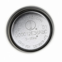
DS1922E-F5# Maxim Integrated Products, DS1922E-F5# Datasheet - Page 12

DS1922E-F5#
Manufacturer Part Number
DS1922E-F5#
Description
IBUTTON TEMP LOGGER 4KBit F5
Manufacturer
Maxim Integrated Products
Series
iButton®r
Datasheet
1.DS1922E-F5.pdf
(44 pages)
Specifications of DS1922E-F5#
Rohs Information
IButton RoHS Compliance Plan
Memory Size
512B
Memory Type
NVSRAM (Non-Volatile SRAM)
Lead Free Status / RoHS Status
Lead free by exemption / RoHS compliant by exemption
The RTC and calendar information is accessed by
reading/writing the appropriate bytes in the register
page, address 0200h to 0205h. For readings to be
valid, all RTC registers must be read sequentially start-
ing at address 0200h. Some of the RTC bits are set to
0. These bits always read 0 regardless of how they are
written. The number representation of the RTC registers
is binary-coded decimal (BCD) format.
The DS1922E’s RTC can run in either 12hr or 24hr
mode. Bit 6 of the Hours register (address 0202h) is
defined as the 12hr or 24hr mode select bit. When high,
the 12hr mode is selected. In the 12hr mode, bit 5 is
the AM/PM bit with logic 1 being PM. In the 24hr mode,
bit 5 is the 20hr bit (20hr to 23hr). The CENT bit, bit 7 of
the Months register, can be written by the user. This bit
changes its state when the years counter transitions
from 99 to 00.
The calendar logic is designed to automatically com-
pensate for leap years. For every year value that is
either 00 or a multiple of 4, the device adds a 29th of
February. This works correctly up to (but not including)
the year 2100.
High-Temperature Logger iButton with 8KB
Data-Log Memory
Note: During a mission, there is only read access to these registers. Bit cells marked “0” always read 0 and cannot be written to 1.
Note: During a mission, there is only read access to these registers. Bit cells marked “0” always read 0 and cannot be written to 1.
12
ADDRESS
ADDRESS
0200h
0201h
0202h
0203h
0204h
0205h
0206h
0207h
______________________________________________________________________________________
Detailed Register Descriptions
BIT 7
CENT
BIT 7
0
0
0
0
0
Timekeeping and Calendar
12/24
BIT 6
BIT 6
0
0
0
10 Years
10 Seconds
10 Minutes
20 Hour
AM/PM
BIT 5
BIT 5
0
10 Date
10 Months
10 Hour
BIT 4
BIT 4
Sample Rate Low
The content of the Sample Rate register (addresses
0206h, 0207h) specifies the time elapse (in seconds if
EHSS = 1, or minutes if EHSS = 0) between two tem-
perature-logging events. The sample rate can be any
value from 1 to 16,383, coded as an unsigned 14-bit
binary number. If EHSS = 1, the shortest time between
logging events is 1s and the longest (sample rate =
3FFFh) is 4.55hr. If EHSS = 0, the shortest is 1min and
the longest time is 273.05hr (sample rate = 3FFFh). The
EHSS bit is located in the RTC Control register at
address 0212h. It is important that the user sets the
EHSS bit accordingly while setting the Sample Rate
register. Writing a sample rate of 0000h results in a
sample rate = 0001h, causing the DS1922E to log
the temperature either every minute or every sec-
ond depending upon the state of the EHSS bit.
BIT 3
BIT 3
Sample Rate High
BIT 2
BIT 2
Single Seconds
Single Minutes
Single Months
Single Hours
Single Years
Single Date
Sample Rate Register
BIT 1
BIT 1
RTC Registers
Sample Rate
BIT 0
BIT 0


