DS1921K# Maxim Integrated Products, DS1921K# Datasheet - Page 3
DS1921K#
Manufacturer Part Number
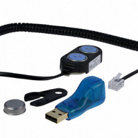
DS1921K#
Description
KIT IBUTTON THERMOCHRON
Manufacturer
Maxim Integrated Products
Series
iButton®r
Specifications of DS1921K#
Lead Free Status / RoHS Status
Lead free / RoHS Compliant
Memory Size
-
Memory Type
-
Lead Free Status / Rohs Status
Lead free / RoHS Compliant
Available stocks
Company
Part Number
Manufacturer
Quantity
Price


ELECTRICAL CHARACTERISTICS (continued)
(V
Note 1:
Note 2:
Note 3:
Note 4:
Note 5:
Note 6:
Note 7:
Note 8:
Note 9:
Note 10: Voltage above which, during a rising edge on IO, a logic 1 is detected.
Note 11: The I-V characteristic is linear for voltages less than 1V.
Note 12: Numbers in bold are not in compliance with the published iButton standards. See the Comparison Table .
Note 13: ε in Figure 15 represents the time required for the pullup circuitry to pull the voltage on the IO pin up from V
Note 14: δ in Figure 15 represents the time required for the pullup circuitry to pull the voltage on the IO pin up from V
Note 15: This number was derived from a test conducted by Cemagref in Antony, France, in July 2000.
Note 16: Total accuracy is Δϑ plus 0.25°C quantization due to the 0.5°C digital resolution of the device.
IO PIN: 1-Wire WRITE
Write-Zero Low Time
(Notes 1, 12)
Write-One Low Time
(Notes 1, 13)
IO PIN: 1-Wire READ
Read Low Time (Notes 1, 14)
Read Sample Time
(Notes 1, 14)
REAL-TIME CLOCK
Frequency Deviation
TEMPERATURE CONVERTER
Tempcore Operating Range
Conversion Time
Thermal Response Time
Constant
Conversion Error
(Notes 16, 17)
Number of Conversions
PUP
= +2.8V to +5.25V, T
PARAMETER
System requirement.
Maximum allowable pullup resistance is a function of the number of 1-Wire devices in the system and 1-Wire recovery
times. The specified value here applies to systems with only one device and with the minimum 1-Wire recovery times. For
more heavily loaded systems, an active pullup such as that found in the DS2480B may be required.
Capacitance on IO could be 800pF when power is first applied. If a 2.2kΩ resistor is used to pull up the data line, 2.5µs
after V
These values are derived from simulation across process, voltage, and temperature and are not production tested.
Input load is to ground.
All voltages are referenced to ground.
V
Voltage below which, during a falling edge of IO, a logic 0 is detected.
The voltage on IO must be less than or equal to V
high threshold of the bus master.
http://www.cemagref.fr/English/index.htm Test Report No. E42
TL
, V
TH
PUP
are a function of the internal supply voltage.
_______________________________________________________________________________________
has been applied, the parasite capacitor does not affect normal communication.
A
= -40°C to +85°C.)
SYMBOL
N
t
t
CONV
t
t
RESP
CONV
MSR
T
W0L
W1L
t
RL
TC
F
Standard speed
Overdrive speed, V
Overdrive speed
Standard speed
Overdrive speed
Standard speed
Overdrive speed
Standard speed
Overdrive speed
-5°C to +46°C
(Note 15)
-40°C to < -30°C
-30°C to +70°C
> +70°C to +85°C
(Notes 4, 18)
ILMAX
CONDITIONS
whenever the master drives the line low.
PUP
> 4.5V
Thermochron iButton
t
t
RL
RL
MIN
-1.3
-1.0
-1.3
-48
-40
8.5
60
19
6
5
1
5
1
+
+
(See the accuracy
graphs.)
TYP
130
15 -
15 -
MAX
+1.3
+1.0
+1.3
2 -
2 -
+46
+85
120
15
15
15
90
2
IL
IL
to V
to the input
TH
UNITS
ppm
.
ms
μs
μs
μs
μs
°C
°C
—
s
3
Related parts for DS1921K#
Image
Part Number
Description
Manufacturer
Datasheet
Request
R

Part Number:
Description:
MAX7528KCWPMaxim Integrated Products [CMOS Dual 8-Bit Buffered Multiplying DACs]
Manufacturer:
Maxim Integrated Products
Datasheet:
Part Number:
Description:
Single +5V, fully integrated, 1.25Gbps laser diode driver.
Manufacturer:
Maxim Integrated Products
Datasheet:
Part Number:
Description:
Single +5V, fully integrated, 155Mbps laser diode driver.
Manufacturer:
Maxim Integrated Products
Datasheet:
Part Number:
Description:
VRD11/VRD10, K8 Rev F 2/3/4-Phase PWM Controllers with Integrated Dual MOSFET Drivers
Manufacturer:
Maxim Integrated Products
Datasheet:
Part Number:
Description:
Highly Integrated Level 2 SMBus Battery Chargers
Manufacturer:
Maxim Integrated Products
Datasheet:
Part Number:
Description:
Current Monitor and Accumulator with Integrated Sense Resistor; ; Temperature Range: -40°C to +85°C
Manufacturer:
Maxim Integrated Products
Part Number:
Description:
TSSOP 14/A�/RS-485 Transceivers with Integrated 100O/120O Termination Resis
Manufacturer:
Maxim Integrated Products
Part Number:
Description:
TSSOP 14/A�/RS-485 Transceivers with Integrated 100O/120O Termination Resis
Manufacturer:
Maxim Integrated Products
Part Number:
Description:
QFN 16/A�/AC-DC and DC-DC Peak-Current-Mode Converters with Integrated Step
Manufacturer:
Maxim Integrated Products
Part Number:
Description:
TDFN/A/65V, 1A, 600KHZ, SYNCHRONOUS STEP-DOWN REGULATOR WITH INTEGRATED SWI
Manufacturer:
Maxim Integrated Products
Part Number:
Description:
Integrated Temperature Controller f
Manufacturer:
Maxim Integrated Products
Part Number:
Description:
SOT23-6/I�/45MHz to 650MHz, Integrated IF VCOs with Differential Output
Manufacturer:
Maxim Integrated Products
Part Number:
Description:
SOT23-6/I�/45MHz to 650MHz, Integrated IF VCOs with Differential Output
Manufacturer:
Maxim Integrated Products
Part Number:
Description:
EVALUATION KIT/2.4GHZ TO 2.5GHZ 802.11G/B RF TRANSCEIVER WITH INTEGRATED PA
Manufacturer:
Maxim Integrated Products
Part Number:
Description:
QFN/E/DUAL PCIE/SATA HIGH SPEED SWITCH WITH INTEGRATED BIAS RESISTOR
Manufacturer:
Maxim Integrated Products
Datasheet: