DS1921K# Maxim Integrated Products, DS1921K# Datasheet - Page 15
DS1921K#
Manufacturer Part Number
DS1921K#
Description
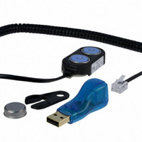
KIT IBUTTON THERMOCHRON
Manufacturer
Maxim Integrated Products
Series
iButton®r
Specifications of DS1921K#
Lead Free Status / RoHS Status
Lead free / RoHS Compliant
Memory Size
-
Memory Type
-
Lead Free Status / Rohs Status
Lead free / RoHS Compliant
Available stocks
Company
Part Number
Manufacturer
Quantity
Price


The Status register holds device status information
and alarm flags. The register is located at address
0214h. Writing to this register does not necessarily
end a mission.
The functional assignments of the individual bits are
explained below. The bits MIP, TLF, THF, and TAF can
only be written to 0. All other bits are read-only. Bit 3
has no function.
Bit 7: Temperature Core Busy (TCB). If this bit reads
0, the DS1921G is currently performing a temperature
conversion. This temperature conversion is either self-
initiated because of a mission being in progress or initi-
ated by a command when a mission is not in progress.
The TCB bit goes low just before a conversion starts
and returns to high just after the result is latched into
the Read-Out register at address 0211h.
Bit 6: Memory Cleared (MEMCLR). If this bit reads 1,
the memory pages 17 and higher (alarm timestamps/
durations, temperature histogram, excluding data-log
memory), as well as the Mission Timestamp, Mission
Samples Counter, Mission Start Delay, and Sample
Rate have been cleared to 0 from executing a Clear
Memory function command. The MEMCLR bit returns to
0 as soon as writing a nonzero value to the Sample
Rate register starts a new mission, provided that the EM
bit is also 0. The memory has to be cleared in order
for a mission to start.
Bit 5: Mission in Progress (MIP). If this bit reads 1, the
DS1921G has been set up for a mission and this mis-
sion is still in progress. A mission is started if the EM bit
of the Control register (address 20Eh) is 0 and a nonze-
ro value is written to the Sample Rate register, address
20Dh. The MIP bit returns from logic 1 to logic 0 when a
mission is ended. A mission ends with the first write
attempt (Copy Scratchpad command) to any register in
ADDRESS
0214h
BIT 7
TCB
______________________________________________________________________________________
MEMCLR
BIT 6
Status Register
BIT 5
MIP
BIT 4
SIP
the address range of 200h to 213h. Alternatively, a mis-
sion can be ended by directly writing to the Status reg-
ister and setting the MIP bit to 0. The MIP bit cannot be
set to 1 by writing to the Status register.
BIT 4: Sample in Progress (SIP). If this bit reads 1, the
DS1921G is currently performing a temperature conver-
sion as part of a mission in progress. The mission sam-
ples occur on the seconds rollover from 59 to 00. The
SIP bit changes from 0 to 1 approximately 250ms
before the actual temperature conversion begins allow-
ing the circuitry of the chip to wake up. A temperature
conversion including a wake-up phase takes maximum
875ms. During this time, read accesses to the memory
pages 17 and higher are permissible but can reveal
invalid data.
Bit 2: Temperature Low Flag (TLF). Logic 1 in the
temperature low flag bit indicates that a temperature
measurement during a mission revealed a temperature
equal to or lower than the value in the Temperature Low
Threshold register. The temperature low flag can be
cleared at any time by writing this bit to 0. This flag
must be cleared before starting a new mission.
Bit 1: Temperature High Flag (THF). Logic 1 in the
temperature high flag bit indicates that a temperature
measurement during a mission revealed a temperature
equal to or higher than the value in the Temperature
High Threshold register. The temperature high flag can
be cleared at any time by writing this bit to 0. This flag
must be cleared before starting a new mission.
Bit 0: Timer Alarm Flag (TAF). If this bit reads 1, a
RTC alarm has occurred (see the Timekeeping section
for details). The timer alarm flag can be cleared at any
time by writing this bit to logic 0. Since the timer alarm
cannot be disabled, the TAF flag usually reads 1 during
a mission. This flag should be cleared before starting a
new mission.
Thermochron iButton
BIT 3
0
BIT 2
TLF
Status Register Map
BIT 1
THF
BIT 0
TAF
15
Related parts for DS1921K#
Image
Part Number
Description
Manufacturer
Datasheet
Request
R

Part Number:
Description:
MAX7528KCWPMaxim Integrated Products [CMOS Dual 8-Bit Buffered Multiplying DACs]
Manufacturer:
Maxim Integrated Products
Datasheet:
Part Number:
Description:
Single +5V, fully integrated, 1.25Gbps laser diode driver.
Manufacturer:
Maxim Integrated Products
Datasheet:
Part Number:
Description:
Single +5V, fully integrated, 155Mbps laser diode driver.
Manufacturer:
Maxim Integrated Products
Datasheet:
Part Number:
Description:
VRD11/VRD10, K8 Rev F 2/3/4-Phase PWM Controllers with Integrated Dual MOSFET Drivers
Manufacturer:
Maxim Integrated Products
Datasheet:
Part Number:
Description:
Highly Integrated Level 2 SMBus Battery Chargers
Manufacturer:
Maxim Integrated Products
Datasheet:
Part Number:
Description:
Current Monitor and Accumulator with Integrated Sense Resistor; ; Temperature Range: -40°C to +85°C
Manufacturer:
Maxim Integrated Products
Part Number:
Description:
TSSOP 14/A�/RS-485 Transceivers with Integrated 100O/120O Termination Resis
Manufacturer:
Maxim Integrated Products
Part Number:
Description:
TSSOP 14/A�/RS-485 Transceivers with Integrated 100O/120O Termination Resis
Manufacturer:
Maxim Integrated Products
Part Number:
Description:
QFN 16/A�/AC-DC and DC-DC Peak-Current-Mode Converters with Integrated Step
Manufacturer:
Maxim Integrated Products
Part Number:
Description:
TDFN/A/65V, 1A, 600KHZ, SYNCHRONOUS STEP-DOWN REGULATOR WITH INTEGRATED SWI
Manufacturer:
Maxim Integrated Products
Part Number:
Description:
Integrated Temperature Controller f
Manufacturer:
Maxim Integrated Products
Part Number:
Description:
SOT23-6/I�/45MHz to 650MHz, Integrated IF VCOs with Differential Output
Manufacturer:
Maxim Integrated Products
Part Number:
Description:
SOT23-6/I�/45MHz to 650MHz, Integrated IF VCOs with Differential Output
Manufacturer:
Maxim Integrated Products
Part Number:
Description:
EVALUATION KIT/2.4GHZ TO 2.5GHZ 802.11G/B RF TRANSCEIVER WITH INTEGRATED PA
Manufacturer:
Maxim Integrated Products
Part Number:
Description:
QFN/E/DUAL PCIE/SATA HIGH SPEED SWITCH WITH INTEGRATED BIAS RESISTOR
Manufacturer:
Maxim Integrated Products
Datasheet: