DS1921K# Maxim Integrated Products, DS1921K# Datasheet - Page 20
DS1921K#
Manufacturer Part Number
DS1921K#
Description
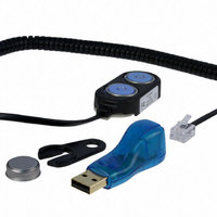
KIT IBUTTON THERMOCHRON
Manufacturer
Maxim Integrated Products
Series
iButton®r
Specifications of DS1921K#
Lead Free Status / RoHS Status
Lead free / RoHS Compliant
Memory Size
-
Memory Type
-
Lead Free Status / Rohs Status
Lead free / RoHS Compliant
Available stocks
Company
Part Number
Manufacturer
Quantity
Price


Thermochron iButton
Figure 9. Address Registers
write command was not recognized by the device. If
everything went correctly, both flags are cleared and
the ending offset indicates the address of the last byte
written to the scratchpad. Now the master can continue
verifying every data bit. After the master has verified the
data, it has to send the Copy Scratchpad command.
This command must be followed exactly by the data of
the three address registers TA1, TA2, and E/S as the
master has read them verifying the scratchpad. As
soon as the DS1921G has received these bytes, it
copies the data to the requested location beginning at
the target address.
The Memory/Control Function Flowchart (Figure 10)
describes the protocols necessary for accessing the
memory and the special function registers of the
DS1921G. An example on how to use these and other
functions to set up the DS1921G for a mission is includ-
ed in the Mission Example: Prepare and Start a New
Mission section. The communication between master
and DS1921G takes place either at standard speed
(default, OD = 0) or at overdrive speed (OD = 1). If not
explicitly set into the overdrive mode, the DS1921G
assumes standard speed. Internal memory access dur-
ing a mission has priority over external access through
the 1-Wire interface. This affects the read memory com-
mands described below. See the Memory Access
Conflicts section for details.
20
______________________________________________________________________________________
TARGET ADDRESS (TA1)
TARGET ADDRESS (TA2)
ENDING ADDRESS WITH
DATA STATUS (E/S)
Memory/Control Function
BIT NUMBER
(READ-ONLY)
T15
AA
T7
7
Commands
T14
T6
6
0
T13
PF
T5
5
After issuing the Write Scratchpad command, the mas-
ter must first provide the 2-byte target address, fol-
lowed by the data to be written to the scratchpad. The
data is written to the scratchpad starting at the byte off-
set T[4:0]. The ending offset E[4:0] is the byte offset at
which the master stops writing data. Only full data
bytes are accepted. If the last data byte is incomplete,
its content is ignored and the partial byte flag (PF) is
set.
When executing the Write Scratchpad command, the
CRC generator inside the DS1921G (see Figure 16) cal-
culates a CRC of the entire data stream, starting at the
command code and ending at the last data byte sent
by the master. This CRC is generated using the CRC-
16 polynomial by first clearing the CRC generator and
then shifting in the command code (0Fh) of the Write
Scratchpad command, the target addresses TA1 and
TA2 as supplied by the master, and all the data bytes.
The master can end the Write Scratchpad command at
any time. However, if the ending offset is 11111b, the
master can send 16 read time slots and receive an
inverted CRC-16 generated by the DS1921G.
Note: The range 200h to 213h of the register page is
protected during a mission. See Figure 6 for the
access type of the individual registers between and
during missions.
T12
T4
E4
4
T11
E3
T3
3
T10
T2
E2
2
Write Scratchpad [0Fh]
T1
T9
E1
1
E0
T0
T8
0
Related parts for DS1921K#
Image
Part Number
Description
Manufacturer
Datasheet
Request
R

Part Number:
Description:
MAX7528KCWPMaxim Integrated Products [CMOS Dual 8-Bit Buffered Multiplying DACs]
Manufacturer:
Maxim Integrated Products
Datasheet:
Part Number:
Description:
Single +5V, fully integrated, 1.25Gbps laser diode driver.
Manufacturer:
Maxim Integrated Products
Datasheet:
Part Number:
Description:
Single +5V, fully integrated, 155Mbps laser diode driver.
Manufacturer:
Maxim Integrated Products
Datasheet:
Part Number:
Description:
VRD11/VRD10, K8 Rev F 2/3/4-Phase PWM Controllers with Integrated Dual MOSFET Drivers
Manufacturer:
Maxim Integrated Products
Datasheet:
Part Number:
Description:
Highly Integrated Level 2 SMBus Battery Chargers
Manufacturer:
Maxim Integrated Products
Datasheet:
Part Number:
Description:
Current Monitor and Accumulator with Integrated Sense Resistor; ; Temperature Range: -40°C to +85°C
Manufacturer:
Maxim Integrated Products
Part Number:
Description:
TSSOP 14/A�/RS-485 Transceivers with Integrated 100O/120O Termination Resis
Manufacturer:
Maxim Integrated Products
Part Number:
Description:
TSSOP 14/A�/RS-485 Transceivers with Integrated 100O/120O Termination Resis
Manufacturer:
Maxim Integrated Products
Part Number:
Description:
QFN 16/A�/AC-DC and DC-DC Peak-Current-Mode Converters with Integrated Step
Manufacturer:
Maxim Integrated Products
Part Number:
Description:
TDFN/A/65V, 1A, 600KHZ, SYNCHRONOUS STEP-DOWN REGULATOR WITH INTEGRATED SWI
Manufacturer:
Maxim Integrated Products
Part Number:
Description:
Integrated Temperature Controller f
Manufacturer:
Maxim Integrated Products
Part Number:
Description:
SOT23-6/I�/45MHz to 650MHz, Integrated IF VCOs with Differential Output
Manufacturer:
Maxim Integrated Products
Part Number:
Description:
SOT23-6/I�/45MHz to 650MHz, Integrated IF VCOs with Differential Output
Manufacturer:
Maxim Integrated Products
Part Number:
Description:
EVALUATION KIT/2.4GHZ TO 2.5GHZ 802.11G/B RF TRANSCEIVER WITH INTEGRATED PA
Manufacturer:
Maxim Integrated Products
Part Number:
Description:
QFN/E/DUAL PCIE/SATA HIGH SPEED SWITCH WITH INTEGRATED BIAS RESISTOR
Manufacturer:
Maxim Integrated Products
Datasheet: