DS1904L-F5# Maxim Integrated Products, DS1904L-F5# Datasheet - Page 4

DS1904L-F5#
Manufacturer Part Number
DS1904L-F5#
Description
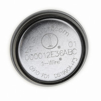
IBUTTON RTC F5 MICROCAN
Manufacturer
Maxim Integrated Products
Series
iButton®r
Datasheet
1.DS1904L-F5.pdf
(13 pages)
Specifications of DS1904L-F5#
Rohs Information
IButton RoHS Compliance Plan
Lead Free Status / RoHS Status
Lead free / RoHS Compliant
Memory Size
-
Memory Type
-
Lead Free Status / Rohs Status
Lead free / RoHS Compliant
Available stocks
Company
Part Number
Manufacturer
Quantity
Price
TIMEKEEPING
A 32.768 kHz crystal oscillator is used as the time base for the real-time clock counter. The oscillator can
be turned on or off under software control. The oscillator must be on for the real time clock to function.
The real-time clock counter is double buffered. This allows the master to read time without the data
changing while it is being read. To accomplish this, a snapshot of the counter data is transferred to a
read/write buffer, which the user accesses.
DEVICE CONTROL BYTE
The on/off control of the 32.768 kHz crystal oscillator is done through the device control byte. This byte
can be read and written through the Clock Function commands.
Device Control Byte
Bits 0 and 1 are hard-wired to read all 0’s.
These bits control/report whether the 32.768 kHz crystal oscillator is running. If the oscillator is running,
both OSC bits will read 1. If the oscillator is turned off these bits will all read 0. When writing the device
control byte both occurrences of the OSC bit should have identical data. Otherwise the value in bit ad-
dress 3 (bold) takes precedence.
These non-volatile bits have no particular function within the chip. They can be read and written under
the control of the application software.
REAL-TIME CLOCK
The real-time clock is a 32-bit binary counter. It is incremented once per second. The real-time clock can
accumulate 136 years of seconds before rolling over. Time/date is represented by the number of seconds
since a reference point, which is determined by the user. For example, 12:00 a.m., January 1, 1970 could
be a reference point.
CLOCK FUNCTION COMMANDS
The “Clock Function Flow Chart” (Figure 5) describes the protocols necessary for accessing the real-time
clock. With only four bytes of real-time clock and one control byte the DS1904 does not provide random
access. Reading and writing always starts with the device control byte followed by the least significant
byte of the time data.
Bit 0 - 1
Bit 2 - 3
Bit 4 - 7
U4
7
U3
6
OSC Oscillator Enable/Disable
Un
0
U2
5
No function
General-purpose user flags
U1
4
OSC
3
OSC
2
1
0
4 of 13
0
0


