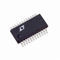
LTC1436AIGN Linear Technology, LTC1436AIGN Datasheet - Page 20

LTC1436AIGN
Manufacturer Part Number
LTC1436AIGN
Description
IC SW REG SYNC STEP-DOWN 24-SSOP
Manufacturer
Linear Technology
Type
Step-Down (Buck)r
Datasheet
1.LTC1436AIGN-PLLPBF.pdf
(28 pages)
Specifications of LTC1436AIGN
Internal Switch(s)
No
Synchronous Rectifier
Yes
Number Of Outputs
1
Voltage - Output
1.19 ~ 9 V
Current - Output
50mA
Frequency - Switching
125kHz ~ 240kHz
Voltage - Input
3.5 ~ 30 V
Operating Temperature
-40°C ~ 85°C
Mounting Type
Surface Mount
Package / Case
24-SSOP
Lead Free Status / RoHS Status
Contains lead / RoHS non-compliant
Power - Output
-
Available stocks
Company
Part Number
Manufacturer
Quantity
Price
Part Number:
LTC1436AIGN#PBF
Manufacturer:
LINEAR/凌特
Quantity:
20 000
Company:
Part Number:
LTC1436AIGN-PLL
Manufacturer:
Linear Technology
Quantity:
135
Part Number:
LTC1436AIGN-PLL
Manufacturer:
LT/凌特
Quantity:
20 000
Part Number:
LTC1436AIGN-PLL#PBF
Manufacturer:
LINEAR/凌特
Quantity:
20 000
APPLICATIONS
LTC1436A
LTC1436-PLL-A/LTC1437A
Minimum On-Time Considerations
Minimum on-time, t
time that the LTC1436A/LTC1437A are capable of turning
the top MOSFET on and off again. It is determined by
internal timing delays and the gate charge required to turn
on the top MOSFET. Low duty cycle applications may
approach this minimum on-time limit. If the duty cycle
falls below what can be accommodated by the minimum
on-time, the LTC1436A/LTC1437A will begin to skip cycles.
The output voltage will continue to be regulated, but the
ripple current and ripple voltage will increase. Therefore
this limit should be avoided.
20
1:N
Figure 11a. 12V Output Auxiliary Regulator Using
Internal Feedback Resistors
ON/OFF
Figure 11b. 5V Output Auxiliary Regulator Using
External Feedback Resistors
1:N
+
INPUT
SECONDARY WINDING
+
Figure 11c. Auxiliary Comparator Configuration
V
SEC
SECONDARY WINDING
R6
R5
V
SEC
R6
R5
AUXON
AUXFB
V
SFB
SEC
LTC1436A
LTC1437A
V
SFB
LTC1436A
LTC1437A
SEC
= 1.19V 1 +
U
–
+
= 1.19V 1 +
ON(MIN)
1.19V REFERENCE
AUXDR
AUXON
( )
AUXFB
LTC1436A
LTC1437A
INFORMATION
AUXDR
AUXON
AUXFB
U
( )
R6
R5
, is the smallest amount of
R6
R5
ON/OFF
> 13V
ON/OFF
AUXDR
W
V
PULL-UP < 8.5V
R8
R7
V
OAUX
+
OUTPUT
= 1.19V 1 +
1436 F11c
U
+
10µF
V
12V
1436 F11a
OAUX
10µF
( )
V
1436 F11b
OAUX
R8
R7
The minimum on-time for the LTC1436A/LTC1437A in a
properly configured application is less than 300ns but
increases at low ripple current amplitudes (see Figure 12).
If an application is expected to operate close to the
minimum on-time limit, an inductor value must be chosen
that is low enough to provide sufficient ripple amplitude to
meet the minimum on-time requirement. To determine the
proper value, use the following procedure:
1. Calculate on-time at maximum supply, t
2. Use Figure 12 to obtain the peak-to-peak inductor ripple
3. Ripple amplitude ∆I
4. L
Choose an inductor less than or equal to the calculated
L
Because of the sensitivity of the LTC1436A/LTC1437A
current comparator when operating close to the minimum
on-time limit, it is important to prevent stray magnetic flux
generated by the inductor from inducing noise on the
current sense resistor, which may occur when axial type
cores are used. By orienting the sense resistor on the
radial axis of the inductor (see Figure 13), this noise will be
minimized.
MAX
(1/f)(V
current as a percentage of I
the calculated t
where I
MAX
Figure 12. Minimum On-Time vs Inductor Ripple Current
to ensure proper operation.
=
OUT
MAX
t
ON MIN
250
400
350
300
200
/V
(
= 0.1/R
IN(MAX)
0
INDUCTOR RIPPLE CURRENT (% OF I
ON(MIN)
)
⎛
⎜
⎝
10
V
IN MAX
SENSE
).
L(MIN)
(
20
∆
.
I
L MIN
(
.
30
)
= (% from Figure 12) (I
–
MAX
V
)
40
OUT
REGION FOR MIN
MAX EFFICIENCY
RECOMMENDED
ON-TIME AND
necessary to achieve
50
⎞
⎟
⎠
60
MAX
1435A F12
)
70
ON(MIN)
14367afb
MAX
=
)


