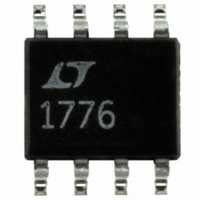
LT1776CS8#TR Linear Technology, LT1776CS8#TR Datasheet - Page 9

LT1776CS8#TR
Manufacturer Part Number
LT1776CS8#TR
Description
IC REG SW STEPDOWN HI EFF 8SOIC
Manufacturer
Linear Technology
Type
Step-Down (Buck)r
Datasheet
1.LT1776CS8PBF.pdf
(20 pages)
Specifications of LT1776CS8#TR
Internal Switch(s)
Yes
Synchronous Rectifier
No
Number Of Outputs
1
Voltage - Output
1.24 ~ 34 V
Current - Output
700mA
Frequency - Switching
200kHz
Voltage - Input
7.4 ~ 40 V
Operating Temperature
0°C ~ 125°C
Mounting Type
Surface Mount
Package / Case
8-SOIC (3.9mm Width)
Lead Free Status / RoHS Status
Contains lead / RoHS non-compliant
Power - Output
-
Available stocks
Company
Part Number
Manufacturer
Quantity
Price
APPLICATIONS
limits the inductor’s current carrying capability as the I
power threatens to overheat the inductor. If applicable,
remember to include the condition of output short circuit.
Although the peak current rating of the inductor can be
exceeded in short-circuit operation, as core saturation per
se is not destructive to the core, excess resistive self-
heating is still a potential problem.
The final inductor selection is generally based on cost,
which usually translates into choosing the smallest physi-
cal size part that meets the desired inductance value,
resistance and current carrying capability. An additional
factor to consider is that of physical construction. Briefly
stated, “open” inductors built on a rod- or barrel-shaped
core generally offer the smallest physical size and lowest
cost. However their open construction does not contain
the resulting magnetic field, and they may not be accept-
able in RFI-sensitive applications. Toroidal style induc-
tors, many available in surface mount configuration, offer
improved RFI performance, generally at an increase in
cost and physical size. And although custom design is
always a possibility, most potential LT1776 applications
can be handled by the array of standard, off-the-shelf
inductor products offered by the major suppliers.
Selecting Freewheeling Diode
Highest efficiency operation requires the use of a Schottky
type diode. DC switching losses are minimized due to its
low forward voltage drop, and AC behavior is benign due
to its lack of a significant reverse recovery time. Schottky
diodes are generally available with reverse voltage ratings
of 60V and even 100V, and are price competitive with other
types.
The use of so-called “ultrafast” recovery diodes is gener-
ally not recommended. When operating in continuous
mode, the reverse recovery time exhibited by “ultrafast”
diodes will result in a slingshot type effect. The power
internal switch will ramp up V
attempt to get it to recover. Then, when the diode has
finally turned off, some tens of nanoseconds later, the V
node voltage ramps up at an extremely high dV/dt, per-
haps 5 to even 10V/ns ! With real world lead inductances,
the V
SW
node can easily overshoot the V
U
INFORMATION
U
IN
current into the diode in an
W
IN
rail. This can
U
SW
2
R
result in poor RFI behavior and if the overshoot is severe
enough, damage the IC itself.
Selecting Bypass Capacitors
The basic topology as shown in Figure 1 uses two bypass
capacitors, one for the V
V
User selection of an appropriate output capacitor is rela-
tively easy, as this capacitor sees only the AC ripple current
in the inductor. As the LT1776 is designed for buck or
step-down applications, output voltage will nearly always
be compatible with tantalum type capacitors, which are
generally available in ratings up to 35V or so. These
tantalum types offer good volumetric efficiency and many
are available with specified ESR performance. The product
of inductor AC ripple current and output capacitor ESR will
manifest itself as peak-to-peak voltage ripple on the output
node. (Note: If this ripple becomes too large, heavier
control loop compensation, at least at the switching fre-
quency, may be required on the V
manding applications, requiring very low output ripple,
may be best served not with a single extremely large
output capacitor, but instead by the common technique of
a separate L/C lowpass post filter in series with the output.
(In this case, “Two caps are better than one”.)
The input bypass capacitor is normally a more difficult
choice. In a typical application e.g., 40V
relatively heavy V
for only a small portion of the oscillator period (low ON
duty cycle). The resulting RMS ripple current, for which
the capacitor must be rated, is often several times the DC
average V
supply as the power switch turns on and off will be related
to the product of capacitor ESR, and the relatively high
instantaneous current drawn by the switch. To compound
these problems is the fact that most of these applications
will be designed for a relatively high input voltage, for
which tantalum capacitors are generally unavailable. Rela-
tively bulky “high frequency” aluminum electrolytic types,
specifically constructed and rated for switching supply
applications, may be the only choice.
OUT
output supply.
IN
current. Similarly, the “glitch” seen on the V
IN
current is drawn by the power switch
IN
input supply and one for the
C
pin.) The most de-
IN
LT1776
to 5V
OUT
9
IN
,


