LTC3865EFE#PBF Linear Technology, LTC3865EFE#PBF Datasheet - Page 10
LTC3865EFE#PBF
Manufacturer Part Number
LTC3865EFE#PBF
Description
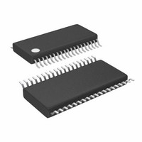
IC BUCK SYNC ADJ DUAL 38TSSOP
Manufacturer
Linear Technology
Type
Step-Down (Buck)r
Datasheet
1.LTC3865EUHPBF.pdf
(38 pages)
Specifications of LTC3865EFE#PBF
Internal Switch(s)
No
Synchronous Rectifier
Yes
Number Of Outputs
2
Voltage - Output
0.6 ~ 5 V
Frequency - Switching
250kHz ~ 770kHz
Voltage - Input
4.5 ~ 38 V
Operating Temperature
-40°C ~ 85°C
Mounting Type
Surface Mount
Package / Case
38-TSSOP Exposed Pad, 38-eTSSOP, 38-HTSSOP
Primary Input Voltage
15V
No. Of Outputs
2
Output Voltage
5V
Output Current
25A
No. Of Pins
38
Operating Temperature Range
-40°C To +85°C
Msl
MSL 1 - Unlimited
Rohs Compliant
Yes
Lead Free Status / RoHS Status
Lead free / RoHS Compliant
Current - Output
-
Power - Output
-
Available stocks
Company
Part Number
Manufacturer
Quantity
Price


LTC3865/LTC3865-1
PIN FUNCTIONS
MODE/PLLIN (Pin 27/Pin 36): Force Continuous Mode,
Burst Mode or Pulse-Skip Mode Selection Pin and External
Synchronization Input to Phase Detector Pin. Connect this
pin to SGND to force both channels in continuous mode of
operation. Connect to INTV
operation. Leaving the pin fl oating will enable Burst Mode
operation. A clock on the pin will force the controller into
continuous mode of operation and synchronize the internal
oscillator with the clock on this pin.
FREQ (Pin 29/Pin 38): This pin sets the frequency of the
internal oscillator. A constant current of 7.5μA is fl owing
out of this pin and a resistor connected to this pin sets
its DC voltage, which in turn, sets the frequency of the
internal oscillator.
RUN1, RUN2 (Pins 30, 11/Pins 1, 17): Run Control
Inputs. A voltage above 1.22V on either pin turns on the IC.
However, forcing either of these pins below 1.22V causes
the IC to shut down the circuitry required for that particular
channel. There are 1μA pull-up currents for these pins.
Once the RUN pin rises above 1.22V, an additional 4.5μA
pull-up current is added to the pin.
10
CC
(QFN/TSSOP)
to enable pulse-skip mode of
SENSE1
Sense Comparator Inputs. The (+) inputs to the current
comparators are normally connected to DCR sensing
networks or current sensing resistors.
SENSE1
Comparator Inputs. The (–) inputs to the current compara-
tors are connected to the outputs.
SGND (Pin 33/Pin 8): Signal Ground. All small-signal
components and compensation components should
connect to this ground, which in turn connects to PGND
at one point. Pin 33 is the Exposed Pad and available for
QFN package.
SGND (Exposed Pad Pin 33/ Exposed Pad Pin 39): Signal
Ground. Must be soldered to PCB, providing a local ground
for the control components of the IC, and be tied to the
PGND pin under the IC.
PGND1, PGND2 (NA/Pins 32, 26): Power Ground Pin.
Connect this pin closely to the sources of the bottom
N-channel MOSFETs, the (–) terminal of C
terminal of C
+
–
, SENSE2
, SENSE2
IN
.
–
+
(Pins 32, 9/Pin 3, 15): Current Sense
(Pins 31, 10/Pins 2, 16): Current
VCC
and the (–)
3865fb
Related parts for LTC3865EFE#PBF
Image
Part Number
Description
Manufacturer
Datasheet
Request
R

Part Number:
Description:
CD ROM LINEARVIEW DATASHEETS
Manufacturer:
Linear Technology

Part Number:
Description:
Standalone Linear Li-Ion Battery Charger with Thermal Regulation in ThinSOT
Manufacturer:
Linear Technology Corporation
Datasheet:
Part Number:
Description:
Low noise, high frequency, 8th order linear phase lowpass filter
Manufacturer:
Linear Technology Corporation
Datasheet:
Part Number:
Description:
Manufacturer:
Linear Technology Corporation
Datasheet:
Part Number:
Description:
Manufacturer:
Linear Technology Corporation
Datasheet:
Part Number:
Description:
Manufacturer:
Linear Technology Corporation
Datasheet:
Part Number:
Description:
Manufacturer:
Linear Technology Corporation
Datasheet:
Part Number:
Description:
Manufacturer:
Linear Technology Corporation
Datasheet:
Part Number:
Description:
Manufacturer:
Linear Technology Corporation
Datasheet:
Part Number:
Description:
Manufacturer:
Linear Technology Corporation
Datasheet:
Part Number:
Description:
Dual and Quad, JFET Input Precision High Speed Op Amps
Manufacturer:
Linear Technology Corporation
Datasheet:
Part Number:
Description:
Manufacturer:
Linear Technology Corporation
Datasheet:
Part Number:
Description:
1, 2, 6 and 8 Channel, 10-Bit Serial I/O Data Acquisition Systems
Manufacturer:
Linear Technology Corporation
Datasheet:
Part Number:
Description:
Manufacturer:
Linear Technology Corporation
Datasheet:
Part Number:
Description:
Universal dual filter building block
Manufacturer:
Linear Technology Corporation
Datasheet: