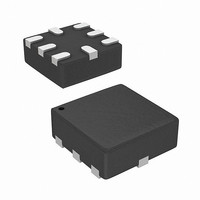
SC195ULTRT Semtech, SC195ULTRT Datasheet - Page 13

SC195ULTRT
Manufacturer Part Number
SC195ULTRT
Description
IC BUCK ADJ .5A 8-MLPQ
Manufacturer
Semtech
Type
Step-Down (Buck)r
Datasheet
1.SC195ULTRT.pdf
(20 pages)
Specifications of SC195ULTRT
Internal Switch(s)
Yes
Synchronous Rectifier
Yes
Number Of Outputs
1
Voltage - Output
0.8 ~ 3.3 V
Current - Output
500mA
Frequency - Switching
3.5MHz
Voltage - Input
2.9 ~ 5.5 V
Operating Temperature
-40°C ~ 85°C
Mounting Type
Surface Mount
Package / Case
8-MLPQ
Lead Free Status / RoHS Status
Lead free / RoHS Compliant
Power - Output
-
Other names
SC195ULTR
Available stocks
Company
Part Number
Manufacturer
Quantity
Price
Company:
Part Number:
SC195ULTRT
Manufacturer:
Semtech
Quantity:
39 722
Part Number:
SC195ULTRT
Manufacturer:
SEMTECH/美国升特
Quantity:
20 000
Applications Information (continued)
To simplify the design, it is recommended to program the
output setting to 1.0V, use resistor values smaller than
10kΩ, and include a feed-forward capacitance calculated
with the equation above. If the output voltage is set to
1.0V, the previous equation reduces to
Example:
An output voltage of 1.3V is desired, but this is not a pro-
grammable option. What external component values for
Figure 1 are needed?
Solution: To keep the circuit simple, set R
current into the OUT pin can be neglected and set the
CTL3-0 pins to 0010 (1.0V setting). The necessary compo-
nent values for this situation are
PWM Operation
Normal PWM operation occurs when the output load
current exceeds the PSAVE threshold. In this mode, the
PMOS high side switch is activated with the duty cycle
required to produce the output voltage programmed by
the CTL pins. An internal synchronous NMOS rectifier
eliminates the need for an external Schottky diode on the
LX pin. The duty cycle (percentage of time PMOS is active)
V
Figure 1 — Application Circuit with External Resistors
IN
Enable
R
C
C
FB
FF
FF
1
8
8
R
C
FB
IN
10
10
2
6
6
V
OUT
IN
CTL3
CTL2
CTL1
CTL0
R
R
V
V
V
FB
FB
SET
OUT
OUT
SC195
1
1
V
V
V
SET
OUT
OUT
0
0
5 .
GND
OUT
5 .
LX
k 3
1
1
2
2
. 5
R
69
L
FB2
X
C
R
nF
FF
FB1
FB2
to 10kΩ so
C
OUT
V
OUT
increases as V
regulation. As the input voltage approaches the pro-
grammed output voltage, the duty cycle approaches
100% (PMOS always on) and the device enters a pass-
through mode until the input voltage increases or the
load decreases enough to allow PWM switching to
resume.
Power Save Mode Operation
When the load current decreases below the PSAVE
threshold, PWM switching stops and the device auto-
matically enters PSAVE mode. This threshold varies
depending on the input voltage and output voltage
setting, optimizing efficiency for all possible load currents
in PWM or PSAVE mode. While in PSAVE mode, output
voltage regulation is controlled by a series of switching
bursts. During a burst, the inductor current is limited to a
peak value which controls the on-time of the PMOS
switch. After reaching this peak, the PMOS switch is dis-
abled and the inductor current decreases to near 0mA.
Switching bursts continue until the output voltage climbs
to V
Switching is then stopped to eliminate switching losses,
enhancing overall efficiency. Switching resumes when
the output voltage reaches the lower threshold of V
and continues until the upper threshold again is reached.
Note that the output voltage is regulated hysteretically
while in PSAVE mode between V
period and duty cycle while in PSAVE mode are solely
determined by V
can result in the switching frequency being much lower
than the PWM mode frequency.
If the output load current increases enough to cause V
to decrease below the PSAVE exit threshold (V
the device automatically exits PSAVE and operates in
continuous PWM mode. Note that the PSAVE high and
low threshold levels are both set at or above V
mize undershoot when the SC195 exits PSAVE. Figure 2
illustrates the transitions from PWM mode to PSAVE
mode and back to PWM mode.
OUT
+2.5% or until the PSAVE current limit is reached.
IN
IN
decreases to maintain output voltage
and V
OUT
until PWM mode resumes. This
OUT
and V
OUT
+ 2.5%. The
SC195
OUT
OUT
to mini-
-2%),
OUT
OUT
13


