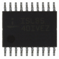
ISL8540IVEZ Intersil, ISL8540IVEZ Datasheet - Page 11

ISL8540IVEZ
Manufacturer Part Number
ISL8540IVEZ
Description
IC REG 2A DC/DC STEP-DN 20HTSSOP
Manufacturer
Intersil
Type
Step-Down (Buck)r
Datasheet
1.ISL8540IVEZ.pdf
(16 pages)
Specifications of ISL8540IVEZ
Internal Switch(s)
Yes
Synchronous Rectifier
Yes
Number Of Outputs
1
Voltage - Output
1.21 ~ 35 V
Current - Output
2A
Frequency - Switching
100kHz ~ 600kHz
Voltage - Input
9 ~ 40 V
Operating Temperature
-40°C ~ 85°C
Mounting Type
Surface Mount
Package / Case
20-TSSOP Exposed Pad, 20-eTSSOP, 20-HTSSOP
Power - Output
3W
Rohs Compliant
Yes
Lead Free Status / RoHS Status
Lead free / RoHS Compliant
Available stocks
Company
Part Number
Manufacturer
Quantity
Price
Company:
Part Number:
ISL8540IVEZ
Manufacturer:
Intersil
Quantity:
74
Applications Information
Product Description
The ISL8540 is a non-synchronous, integrated FET 2A step
down regulator which operates from an unregulated input of
9V to 40V. The output voltage is user-adjustable with a pair
of external resistors. Frequency of operation is adjustable
from 100kHz to 600kHz set by RTCT. An external signal with
higher frequency can be injected to SYNCH to synchronize
the controller.
The buck controller drives an internal N-Channel MOSFET
and requires an external diode to deliver load current up to
2A. A Schottky diode is recommended for improved
efficiency and performance over a standard diode. The
converter output is regulated down to 1.21V from an input
source. These features make the ISL8540 ideally suited for
telecommunication power applications.
The PWM control loop uses a single output voltage loop with
input voltage feed forward which simplifies feedback loop
compensation and rejects input voltage variation. External
feedback loop compensation allows flexibility in output filter
component selection.
The buck regulator is equipped with a lossless current limit
scheme. The current limit in the buck regulator is achieved
by monitoring the drain-to-source current of the internal
switching power MOSFET. The current limit threshold is
internally set at 4.5A peak. Additional features include
programmable soft-start to support proper start-up of wide
output capacitance range.
Start-Up and Shut-Down
When the EN pin is connected to a logic high, the ISL8540 is
in the shut-down mode. All the control circuitry and both
MOSFETs are off, and V
total input current is less than 110µA.
When the EN pin is tied to GND, and V
approximately 9V, the regulator begins to switch. The output
voltage is gradually increased to ensure proper soft-start
operation.
When the EN reaches logic LOW, the regulator repeats the
start-up procedure, including the soft-start function. Connect
a capacitor from SS pin to ground. This capacitor, along with
an internal 10µA current source sets the soft-start interval of
the converter, t
Operating Frequency
The ISL8540 can operate at switching frequencies from
100kHz to 600kHz. A resistor tied from the RTCT pin to VIN
C
SS
[
μF
]
≈
8.3 t
⋅
SS
SS
.
s [ ]
OUT
11
falls to zero. In this mode, the
IN
reaches
(EQ. 1)
ISL8540
and a capacitor from RTCT to GND are used to program the
switching frequency through Equation 2.
Caution: When the ISL8540 is in disabled state, the voltage
across RTCT pin will reach V
voltage rating of the RTCT capacitor is rated as high as the
input voltage.
Output Voltage Selection
The output voltage of the regulator can be programmed via
an external resistor divider that is used to scale the output
voltage relative to the internal reference voltage and feed it
back to the inverting input of the error amplifier. Refer to
Figure 28.
The output voltage programming resistor, R
the value chosen for the feedback resistor and the desired
output voltage of the regulator. The value for the feedback
resistor is typically between 1kΩ and 10kΩ.
If the output voltage desired is 1.21V, then R
unpopulated.
Fault Protection
The ISL8540 monitors the output of the regulator for
overcurrent and undervoltage events. The ISL8540 also
provides protection from excessive junction temperatures.
Overcurrent Protection
The overcurrent function protects the switching converter from
a shorted output by monitoring the current flowing through the
upper MOSFETs.
Upon detection of overcurrent condition, the upper MOSFET
will be immediately turned off and will not be turned on again
until the next switching cycle. Upon detection of the initial
overcurrent condition, the overcurrent fault counter is set to
1 and the overcurrent condition flag is set from LOW to
HIGH. If, on the subsequent cycle, another overcurrent
condition is detected, the OC fault counter will be
incremented. If there are 16 sequential OC fault detections,
the regulator will be shut down under an overcurrent fault
condition. An overcurrent fault condition will result with the
regulator attempting to restart in a hiccup mode with the
delay between restarts being 4 soft-start periods. At the end
of the fourth soft-start wait period, the fault counters are
reset and soft-start is attempted again. If the overcurrent
condition goes away prior to the OC fault counter reaching a
count of four, the overcurrent condition flag will set back to
LOW.
If the overcurrent condition flag is HIGH and the overcurrent
fault counter is less than four and an undervoltage event is
detected, the regulator will be shut down immediately.
C
R
1
3
[
nF
=
------------------------------------- -
V
]
R
OUT
=
2
---------------- -
R kΩ
×
6.25
[
1.21V
–
1.21V
]
⎛
⎝
----------------------------- - 0.3
f
OSC
1000
[
kHz
]
–
IN
voltage. Make sure that the
⎞
⎠
3
, will depend on
3
is left
September 9, 2008
FN6495.5
(EQ. 3)
(EQ. 2)


