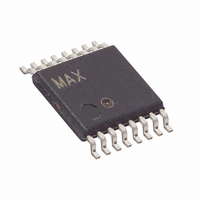
MAX3353EEUE+T Maxim Integrated Products, MAX3353EEUE+T Datasheet - Page 14

MAX3353EEUE+T
Manufacturer Part Number
MAX3353EEUE+T
Description
IC CHARGE PUMP USB OTG 16TSSOP
Manufacturer
Maxim Integrated Products
Datasheet
1.MAX3353EEUET.pdf
(21 pages)
Specifications of MAX3353EEUE+T
Applications
Charge Pump, USB
Voltage - Input
2.6 ~ 5.5 V
Number Of Outputs
2
Operating Temperature
-40°C ~ 85°C
Mounting Type
Surface Mount
Package / Case
16-TSSOP
Maximum Operating Temperature
+ 85 C
Mounting Style
SMD/SMT
Minimum Operating Temperature
- 40 C
Lead Free Status / RoHS Status
Lead free / RoHS Compliant
Voltage - Output
-
Lead Free Status / Rohs Status
Lead free / RoHS Compliant
interrupt edge, and interrupt latch address maps. Bit
configuration is shown in Tables 9, 10, and 11.
The manufacturer and ID registers are read-only regis-
ters (Table 12).
USB On-the-Go Charge Pump with Switchable
Pullup/Pulldown Resistors
Table 3. Control Register Address Map
Table 4. Control Register 1 (10h)
Table 6. Status Register Address Map
(—) = don’t know
14
REGISTER ADDRESS
REGISTER ADDRESS
NUMBER
Control 1
Control 2
Status
BIT
______________________________________________________________________________________
0
1
2
3
4
5
6
7
Manufacturer and ID Register Address Map
DM_PULLUP
DP_PULLUP
IRQ_MODE
PULLDWN
PULLDWN
SYMBOL
ACONN
BDISC_
DM_
DP_
10h
11h
13h
—
—
OPERATION
Not used
Interrupt pin open-drain/push-pull:
0 = open drain
1 = push/pull
0 = disable
1 = enable
Not used
D+ pullup (high priority)
0 = D+ pullup unconnected
1 = D+ pullup connected
D- pullup:
0 = D- pullup unconnected
1 = D- pullup connected
D+ pulldown:
0 = D+ pulldown unconnected
1 = D+ pulldown connected
D- pulldown:
0 = D- pulldown unconnected
1 = D- pulldown connected
BIT 7
BIT 7
0
0
0
BIT 6
BIT 6
0
0
0
BIT 5
BIT 5
0
0
0
POWER-UP REGISTER STATUS
POWER-UP REGISTER STATUS
Five external capacitors are recommended for proper
operation. Bypass V
ceramic capacitor. Bypass V
1µF low-ESR ceramic capacitor. For the internal charge
pump, use a 0.1µF ceramic capacitor between C+ and C-.
Table 5. Control Register 2 (11h)
BIT 4
NUMBER
BIT 4
—
0
0
BIT
0
1
2
3
4
5
6
7
V
V
V
BIT 3
BUS_DISCHG
BIT 3
V
SYMBOL
BUS_CHG1
BUS_CHG2
BUS_DRV
—
0
0
SDWN
—
—
—
L
and V
BIT 2
BIT 2
OPERATION
Puts part in shutdown mode:
0 = operating
1 = shutdown mode
Charge V
generator for 105ms:
0 = current generator OFF
1 = current generator ON
(automatically turned off after
105ms)
Charge V
generator:
0 = current generator OFF
1 = current generator ON
Drive V
0 = V
1 = V
pump
Discharge V
0 = Resistor disconnected
1 = Resistor connected
Not used
Not used
Not used
—
0
0
BUS
TRM
External Capacitors
BUS
BUS
BUS
and V
BUS
BUS
not driven
connected to the charge
to GND with a 0.1µF
through charge pump
BUS
BIT 1
BIT 1
through a current
through a current
—
0
0
CC
through a resistor:
to GND with a
BIT 0
BIT 0
—
0
1


