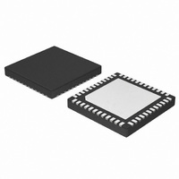
NCP4201MNR2G ON Semiconductor, NCP4201MNR2G Datasheet - Page 30

NCP4201MNR2G
Manufacturer Part Number
NCP4201MNR2G
Description
IC CTLR VR11.1 4PH PMBUS ITF
Manufacturer
ON Semiconductor
Datasheet
1.NCP4201MNR2G.pdf
(32 pages)
Specifications of NCP4201MNR2G
Applications
Controller, Intel VR11, VR11.1
Voltage - Input
1.7 ~ 24 V
Number Of Outputs
4
Voltage - Output
0.375 ~ 1.6 V
Operating Temperature
0°C ~ 85°C
Mounting Type
Surface Mount
Package / Case
48-TQFN Exposed Pad
Lead Free Status / RoHS Status
Lead free / RoHS Compliant
Available stocks
Company
Part Number
Manufacturer
Quantity
Price
Company:
Part Number:
NCP4201MNR2G
Manufacturer:
ON Semiconductor
Quantity:
2 000
Code
0xDF
Cmd
0xE0
0xE1
0xE2
0xE3
0xE4
0xE5
0xE6
0xF5
0xF6
0xF9
R/W
R/W
R/W
R/W
R/W
R/W
R/W
R/W
R/W
R/W
R/W
R/W
Default
0x0002
0x0002
0x00
0x00
0x00
0x10
0x10
0x10
0x10
0x10
0x00
Load−line Set
PWRGD Hi Threshold
PWRGD Lo Threshold
Current Limit Threshold
Phase Bal SW1
Phase Bal SW2
Phase Bal SW3
Phase Bal SW4
V
V
Mask ALERT
MON
MON
Description
FAULT Limit
Warn Limit
http://onsemi.com
Bytes
#
1
1
1
1
1
1
1
1
2
2
1
30
V
This value sets the internal load−line attenuation DAC value. The
maximum load−line is controlled externally by setting the gain of the
current sense amplifier as explained in the applications section. This
maximum load−line can then be adjusted from 100% to 0% in 30
steps. Each LSB represents a 3.226% change in the load−line.
00000 = No load−line
10000 = 51.6% of external load−line
11111 = 100% of external load−line
This value sets the PWRGD Hi Threshold and the CROWBAR
Threshold:
Code = 00, PWRGD HI = 300 mV (default)
Code = 01, PWRGD HI = 250 mV
Code = 10, PWRGD HI = 200 mV
Code = 11, PWRGD HI = 150 mV
This value sets the PWRGD Lo Threshold:
Code = 000, PWRGD Lo = −500 mV (default)
Code = 001, PWRGD Lo = −450 mV
Code = 010, PWRGD Lo = −400 mV
Code = 011, PWRGD Lo = −350 mV
Code = 100, PWRGD Lo = −300 mV
Code = 101, PWRGD Lo = −250 mV
Code = 110, PWRGD Lo = −200 mV
Code = 111, PWRGD Lo = −150 mV
This value sets the internal current limit adjustment value. The default
current limit is programmed using a resistor to ground on the LIMIT
pin. The value of this register adjusts this value by a percentage
between 50% and 146.7%. Each LSB represents a 3.33% change in
the current limit threshold.
11111 = 146.7% of external current limit
10000 = 100% of external current limit (default)
00000 = 50% of external current limit
These values adjust the gain of the internal phase balance amplifiers.
The nominal gain is set to 5. These registers can adjust the gain by
±25% from 3.75 to 6.1718.
Code = 00000, Gain of 3.75
Code = 10000, Gain of 5 (default)
Code = 11111, Gain of 6.1718
These values adjust the gain of the internal phase balance amplifiers.
The nominal gain is set to 5. These registers can adjust the gain by
±25% from 3.75 to 6.1718.
Code = 00000, Gain of 3.75
Code = 10000, Gain of 5 (default)
Code = 11111, Gain of 6.1718
These values adjust the gain of the internal phase balance amplifiers.
The nominal gain is set to 5. These registers can adjust the gain by
±25% from 3.75 to 6.1718.
Code = 00000, Gain of 3.75
Code = 10000, Gain of 5 (default)
Code = 11111, Gain of 6.1718
These values adjust the gain of the internal phase balance amplifiers.
The nominal gain is set to 5. These registers can adjust the gain by
±25% from 3.75 to 6.1718.
Code = 00000, Gain of 3.75
Code = 10000, Gain of 5 (default)
Code = 11111, Gain of 6.1718
V
Bit
MON
7
6
5
4
MON
FAULT Limit
Warn Limit
Mask V
Mask I
Name
Res
Res
OUT
OUT
Masks any ALERT caused by bits in Status
V
Masks any ALERT caused by bits in Status
I
OUT
OUT
Register.
Comment
Register.
Description


